Path Editing Concepts
Path Types
Over half of the entity types you can create with WED are created by drawing geometric shapes we generically refer to as a path or curve. You will be drawing a LOT of paths in WED, so becoming familiar with all the ways you can create and edit paths will help you work quicker and more efficiently. This section discusses path creation and editing.
There are two types of paths you can create in WED:
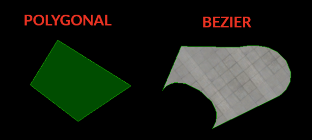
- a POLYGONAL Path (straight segments only)
- a BEZIER Path (can have curved segments)
A POLYGONAL path has no curves, it is literally connect the dots as shown at lower left. BEZIER Paths CAN have curves, but do not have to; therefore, a BEZIER path may look the same as a POLYGONAL path. The example bezier path below right does have curves for illustration.
The following WED tools/entities are defined using Bezier Paths and may have curves:
- Taxiway Tool
- Taxiline Tool
- Hole Tool
- Facades
- Strings
- Lines
- Polygons
- Roads
...and these tools/entities use Polygonal Paths and can have no curves:
- Forests
- Boundaries
- Taxi Routes
- Forests
- Exclusion Polys
- Shapes
Path Topology
Parts of a Path, Nodes, Segments and Handles
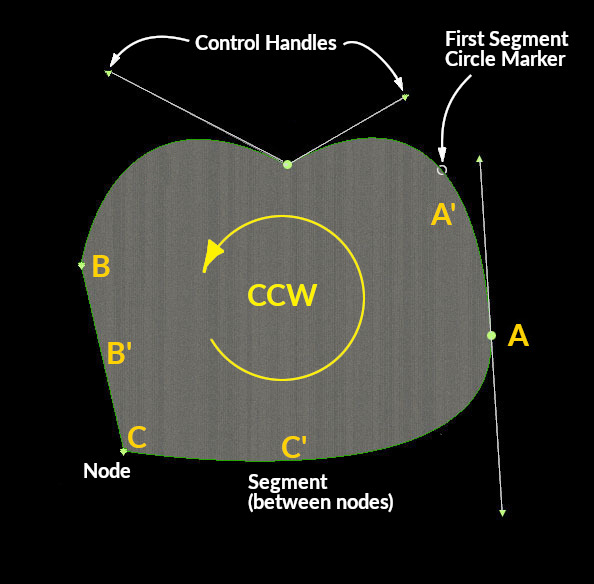
Next we discuss the parts that make up a path and the relevant terminology to describe each. You will see these terms used throughout the manual. Refer to the image at right for the following concepts.
Every path is made up up nodes and segments. A segment is between two nodes. Every path has a First Segment. For POLYGONAL paths, all segments are straight and there's nothing more to it; however, for BEZIER paths, nodes can optionally have up to 2 control handles to create curved segments on either side of the node. Nodes and Control handles may be manipulated graphically with the mouse by click-dragging them around.
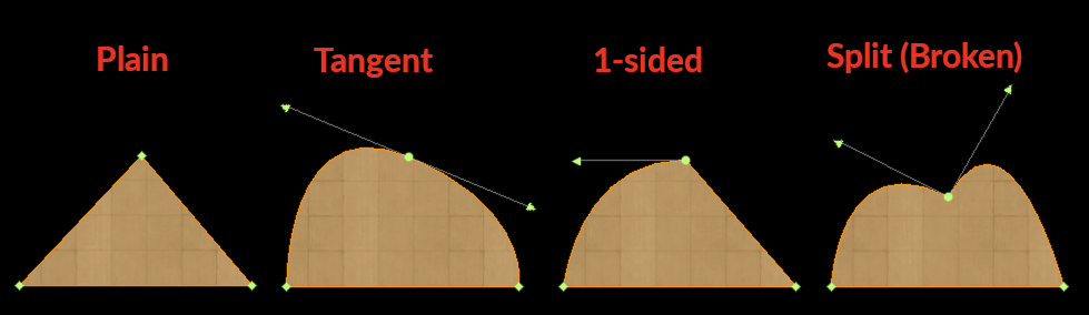
Bezier control handles on a node may be configured in four ways to create the shape you need at that node. The image further below shows how these control handles may be configured in WED and the terms we use to describe each configuration. You can quickly and easily convert between the various control handle configurations using the mouse and modifier keys, so drawing is quick and efficient. These techniques to change the control handle configuration at a node are described further below.
Additionally, paths have directionality. This becomes relevant and important when configuring facades, jetways and adding edge lighting and lines to taxiways. For a given NODE in a closed path, A, the segment emanating from it in the CCW (Counter Clockwise) direction (A') is associated with that node and called the Node Segment for that node. Conversely, for a given SEGMENT (B'), its Segment Node would be node B, etc. For closed paths, you can visualize CCW and CW directions relatively easy; however, for open paths, you need to know which END of the path is the first segment to determine its directionality, i.e. downstream path segments follow the first segment. This allows you do identify nodes and their associated segments in open paths more easily when setting segment properties.
NOTE
It is IMPORTANT to note, that WED assigns path directionality to the path immediately after creation, not in the order you add points. You can add a series of path points in any direction you like, BUT when you complete the path, then WED will re-evaluate the final path, select a first segment, and associate segments with nodes using the CCW paradigm discussed above.
Taxiway edge Lights and lines, as well as facade walls/segments are configured per segment; HOWEVER, you cannot select a segment, only a node, so understanding which segments will be affected based on which node is selected is important.
Bezier Node/Handle Configurations
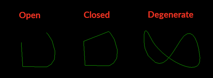
Before we discuss creating paths, we quickly need to mention open paths, closed paths, and degenerate paths. Open paths have 1 segment missing. Closed paths require 3-nodes minimum and fully enclose an area. Degenerate paths have segments that cross and are invalid and are to be avoided. The image below left illustrates each condition.
WED entities that are areas by nature require closed, non-degenerate paths and WED will auto-close the paths for you when you complete the shape. Other entities defined with bezier curves, but not required to be closed, such as fence-lines, may be open or closed. For these entities, WED will not auto-close the path for you; however, you have the option in the attributes panel to toggle the path between open or closed, in which case, WED will fill in the final segment for you. This is shown below right.
Closed checkbox in Attributes
Bezier Path Shaping
A bezier path is created by a series of single clicks to create plain nodes, or a click-drag to create a tangent node. You may, in the middle of path creation, use modifier keys to change the node handle configuration while editing the path. This is typical and normal and the key combos are described in the next section below. The video clip at right shows control handle editing using the modifier keys while creating a closed path.
For auto-close type Bezier paths, WED will show the auto-close segment in a thinner line-weight as you are editing. This can be seen in the example video at right also. For non-autoclose bezier paths, no auto-close segment will be shown.
In the video at right you may notice the nodes and control handle arrows appear/disappear while creating the curve. This is because during path creation, the control handles and nodes will only be displayed when a modifier key is pressed, allowing you to change the control handle configuration. When you are ready to complete the editing, then there are four ways to complete the path, and only after at least 3 nodes have been created.
- Hitting the ENTER key
- Double clicking the mouse.
- Selecting another tool
- Clicking on the first point
Once the path is complete, you can use the Vertex Tool to edit any of the points again. Some authors prefer to edit the control handles as they go, as shown in the video at right, whereas other authors will just single click quickly to create a basic polygonal style path and then go back and convert the nodes as required to refine and finalize the path. Both methods are fine. The next section discusses how the Node handle configurations may be changed using the modifier keys. It is important to get comfortable with these modifier keys to create high quality paths.
Converting Node Handles
Click to Enlarge
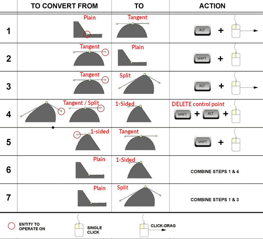
Converting Node handle configurations is extremely common in WED editing. With no modifier keys pressed while creating paths, only Tangent and Plain type Nodes will be created as you click/click-drag.
After the path is created, and using the Vertex Tool, you can further edit the node handle configurations using a combination of keystrokes and mouse actions. The chart at right shows the various conversions you can perform and the keystroke and mouse actions required to do so. It takes a bit of practice to get used to these, but soon becomes second nature.
Adding/Deleting Nodes
You can add and delete nodes easily. Deleting nodes is as simple as selecting the nodes with the vertex tool and hitting the DELETE key, or using the menu command EDIT > CLEAR. To add nodes to a segment, you have two options. The first is to simply OPTION-click on a segment somewhere and a point will be added there. Alternatively, you can select the two nodes at either end of the segment and use the EDIT > SPLIT command (or its key shortcut), and WED will add a node in between the end nodes of the segment, effectively splitting the original segment into two segments. The SPLIT command will split every segment that have both its endpoints selected, so you can split multiple segments simultaneously with a single command
Cut/Split a Closed Paths
You can cut / trim a closed path, splitting it into multiple pieces by using the Vertex tool to select two nodes NOT adjacent to one another, and then use the EDIT > SPLIT command (CTRL / ⌘ E) to effect a straight line CUT between the two selected nodes. The clip at left illustrates this technique.
In this clip, the SPLIT command was used twice. The first split was used to split the curve segements to create nodes in the middle of those segments so that we could cut the original path between the new nodes, and the second SPLIT command used to actually split the path into two paths, thereby allowing you to orient the textures independently.
In both these cases, the key-shortcut (CTRL / ⌘ E) was used to effect the SPLIT command, so the editing is quite quick.
Split Path at Vertex
A continuous single path may be split into multiple paths at a single vertex, where one shared vertex on the single path becomes two overlapping (coincident) nodes on separate paths after the split and may be manipulated individually after. To split a path at a vertex, simply select a single node with the Vertex tool and execute the EDIT > SPLIT menu command (CMD-E key). This feature is useful for modifying STRING paths with acute angles and offset objects as shown below.
Creating Holes
You can create hole paths within other closed paths by using the Holes tool. The path you want to create a hole in must be selected first and the hole path must be fully contained inside the enclosing shape, i.e. the hole path cannot cross the containing path boundary. Hole paths are bezier types and are drawn in the same way as regular paths. The video at right shows placing a hole inside another path, and how it must be fully contained within that path.
Texture Orientation
Closed paths that have textures (Taxiways and POLs/polygons) may have their texture's rotational orientation changed. To do this, you select the closed area, then hold down the SHIFT key while you click-drag anywhere inside the shape. The texture will rotate as you drag the mouse around. The video at right illustrates this technique.