Facade Tool
General Overview
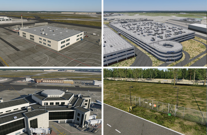
Facades are a powerful feature of WED to create differing shaped structures of the same style by only drawing and configuring a path and letting X-Plane fill in the pieces to complete the structure. Facades are commonly used to create airport terminals, parking garages, fences, hangers, office buildings, apartments, and a whole host of other style structures. Below are some examples of facade use in X-Plane to create structures.
Facade structures are algorithmically assembled from pre-built facade pieces. The path you draw and how you configure the segments of the path determines the final look. Each facade style consists of a finite set of pieces that can be used with that facade and the number of pieces available varies from facade to facade. Some facades have more pieces to use than others and some only have one. (simple fence). Facade pieces are applied per path segment (between nodes). Segments are selected by selecting their Segment Node. (See the Path Editing > Topology section of the manual for more info on the "node-segment" relationship).
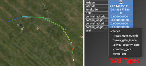
Path segments in facades are called Walls and the available pieces are called Wall Types. If the facade have multiple wall types available, then with a node selected, you can select the Wall type that populate that node's associated segment. Some wall types are designed to repeat along the path segment, like a section of fencing, while other pieces will not repeat, such as a gate in the fence. The image below illustrates the concept of path segments as wall types.
The topmost example fence path have only 3 segments. WED will assign a color to each unique wall type (based on its order in the Wall selection menu); therefore in this example, we can see there are only two colors (red / yellow), so we know two wall types are applied. The red segment is a repeating texture here, whereas the yellow segment is not, it has been set to be a small gate in the Attributes panel. As such, X-Plane has stretched that gate texture to fill the whole segment, creating a very wide (and unrealistic) gate.
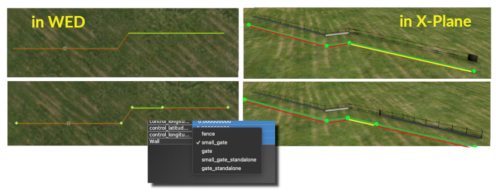
In the bottom example, the yellow segment was split into two segments, and one node moved to provide a more realistic width for a gate, and the remaining segment was set back to a fence Wall Type. This technique would also be used to configure an entry porch on a building, or specify one wall of a building facade to have windows, etc. Quality facade creation is all about placing nodes in the correct spot for the right Wall type. When you place a facade path, you simply have to select any node and look at its Wall Attribute pulldown to see what wall options that facade has. It may have only one, it may have more. The fence example shown above have 5 wall-type options, etc.
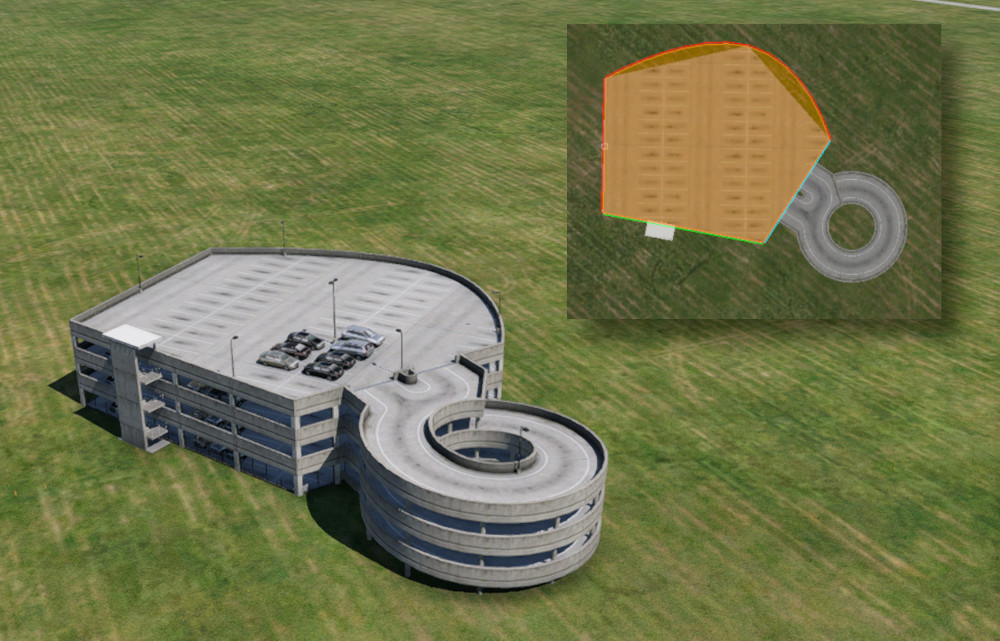
Differing Wall Styles are not necessarily just differing textures, wall segments may also have attached objects. In the example below, we set some segments of a Parking Garage facade to have stairs and an on-Ramp. Note that WED does not render curved Facade segments in the Map View, but they are indeed implemented in X-Plane.
Click to Enlarge
Facades are either open or closed path types depending on their design. Fences are an example of an open path type, and any building with a roof is an example of a closed path type. WED will automatically close paths for facade types that are required to be closed. You can filter in WEDs asset browser by *.fac to see all the default facades available. When you select a facade in the Asset Browser, the preview window will render an example of that style as well as some important information which we discuss next.
Facade preview
Click to Enlarge
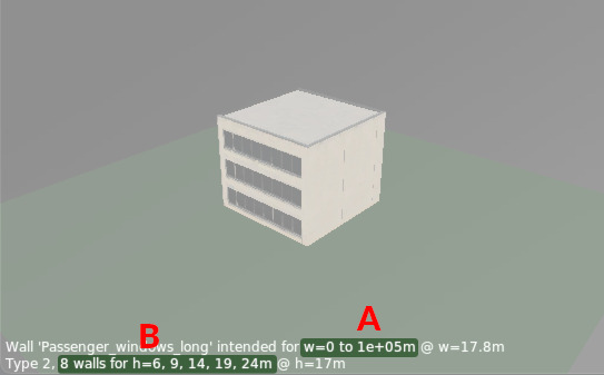
When it comes to facades, the Preview Window takes on a bit more importance as it provides important information about about the available heights supported by that facade, as well as allowing you to preview how various wall-lengths and heights will appear. The example image at right shows two text fields in the preview window. The first field, A tells you the range of wall lengths the facade supports. For most building facades, this value is from zero to really long; however, other facades such as jetways have limited max lengths. This parameter will let you know the range its designed for.
The second field, B; however, tells you both the number of wall types and wall heights available. When you set the height attribute for a facade path, X-Plane will select the nearest height available from this heights list, rounding both up/down as required. If you set a facade height of 10m for this example facade, X-Plane would select the 9m high version. If you set it to it to 12m, X-Plane would round up and select the 14m height version, etc. Further, if you selected a node and then opened the Wall type menu, there would be 8 wall type options to choose from.
Another unique feature with Facade Previews is you can use the Right Mouse Button while you drag the mouse in the preview window, and dragging left/right will alter the preview Wall Length, D, and dragging up/down will alter the preview Wall Height, C. This effect is shown in the clip at left.
Remember that X-Plane builds facades algorithmically based on the length of path segments and the facade height attribute you enter. This is a convenience tool that allows you to have a reasonable idea of how X-Plane will render wall segments and select facade heights.
Finally, to preview the various wall types available, simply rotate the Preview model round and round. Whenever a wall face is not facing the preview camera, WED will swap that face to another wall style so you'll see it when that wall faces the camera again. The first field of the meta-text will tell you the wall style of the face most closely facing the camera, so it will change as you rotate the 3D preview. In the example clip at left, the Wall style, Passenger_windows_long is currently the wall face most closely facing the camera. This is very helpful for knowing what your wall segments will look like.
NOTE
The height preview value (parameter C above) affects where the center of rotation of the preview window will be. If the facade is at the bottom of the preview window and you are having trouble getting the facade to center in the view, then reduce the preview height (Right Mouse > Up/down).
Facade Wall Types
Wall Types are the facade pieces you have to work with for a given facade. They are enumerated in a pull-down menu for the Wall attribute of a facade node. This means you have to select a facade node(s) in order to see the Wall attribute and access the menu.
When you choose a wall type for a selected node, its associated segment is assigned that wall type. WED will assign a unique color marker to each wall type in the map view. The color assigned is based on the wall type's order in the pull-down menu and nothing else. The example at right shows the first 5 differing wall types applied to the 5 path segments, with red=fence, yellow=1-way-gate-outside, and green=1-way-gate-inside, etc.
Facade Heights
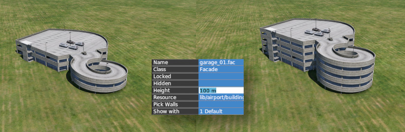
Facades have a Height Attribute to configure their height. While you CAN enter any number here, it is more of a request to "Select an available facade height closest to this value" setting. Because facades are created from pre-built pieces of fixed sizes, then the range of heights any particular facade can be is dependent on the available pieces created for that facade. For example, in the image below, the facade path is the same in WED, but in the left-side version, its height attribute was set to 1m, and in the right side version, it was set to 100m. Fortunately, WED's Preview Window will tell you that range of heights available for any given facade.
Facade Assembly Logic
The following information is NOT necessary for authoring quality facades; however, it may prove interesting or of value for those curious about how X-Plane selects facade pieces to create facades. For context, just know that facade designers create "end pieces" and "middle pieces" and then, in the facade definition file, specify the allowable combinations of these pieces. X-Plane refers to this list of allowable combinations to build the final facade, so the more variations provided by the facade designer, the more flexible the final design can be.
How X-Plane Selects Facade Panels and Floors
The algorithm for selecting panels and floors is the same horizontally and vertically, and goes like this:
- All end tiles are used before any middle tiles.
- End tiles are equally balanced on both ends; for an odd number of tiles, the left/bottom end is preferred.
- Only middle tiles can be repeated.
- Middle tiles are used in left-to-right or bottom-to-top order.
- Middle tiles will be split to match their left-right edges where possible.
Example: this horizontal stripe represents 9 panels: ABC = left panels, 123 = middle panels, XYZ = right panels. So the facade texture is organized as:
ABC123XYZ
This is the set of geometry created as the number of panels is increased; spaces represent X-Plane inserting an additional quad to form the shape.
A
A Z
AB Z
AB YZ
ABC YZ
ABC XYZ
ABC1 XYZ
ABC1 3XYZ
ABC123XYZ     <= exact match, only one quad
ABC12 23XYZ
ABC123 23XYZ
ABC123 123XYZ
ABC123 1 123XYZ
ABC123 12 123XYZ
ABC123 123 123XYZ
ABC123 123 1 123XYZ
Facade Optimization
Facade performance is typically limited by the amount of free memory, not framerate. That is, on most machines, a complex project with a large number of facades will exhaust memory before frame-rate becomes a problem. Most of these tips therefore focus on memory optimizations. (The smallest RAM footprint does also turn into lower vertex count, which is good for frame rate too.)
Correct Winding Order
Facades must be wound counter-clockwise, per the DSF specification. If your facade building’s roof is only visible when TWO_SIDED is set to 1, your facade is wound backward!
No Duplicate Vertices
Do not duplicate any vertices in the facade. Do not repeat the first vertex as the last vertex; a square facade should have IS_RING 1 and contain only four vertices in the DSF. X-Plane will “close” your loop for you. Avoid points in a facade that do not define the shape. For example:
1----2----3
|         |
5---------4
Sloped Roofs
Sloped roofs have some extra requirements:
- No duplicate points, and no “straight” points (see above).
- The roof is built out of a floor, so most times you will want at least two floors.
- The roof should not fold in on itself.
- If the facade is wound wrong, sloped roofs will not work.
Reducing Mesh Complexity
The facade engine can consolidate adjacent panels, but it must use more geometry to repeat panels. For this reason, it is best to make a facade wall that contains enough texture and panels to model the largest wall in your facade without repeating/duplicating texture space. A facade can be built in as few as 1-4 quads when geometry is cut, but if the panels are small, repeating the panels burns through a lot of memory. The facade engine is most efficient when you do not use sloped roofs, the facade is convex in footprint, and the wall definitions match the real size of the facade both vertically and horizontally.
TWO_SIDED
Do not use TWO_SIDED for buildings; use one sided geometry and fix your winding order if necessary. TWO_SIDED is intended only for fences.