Ground Markings
General
Click to Enlarge
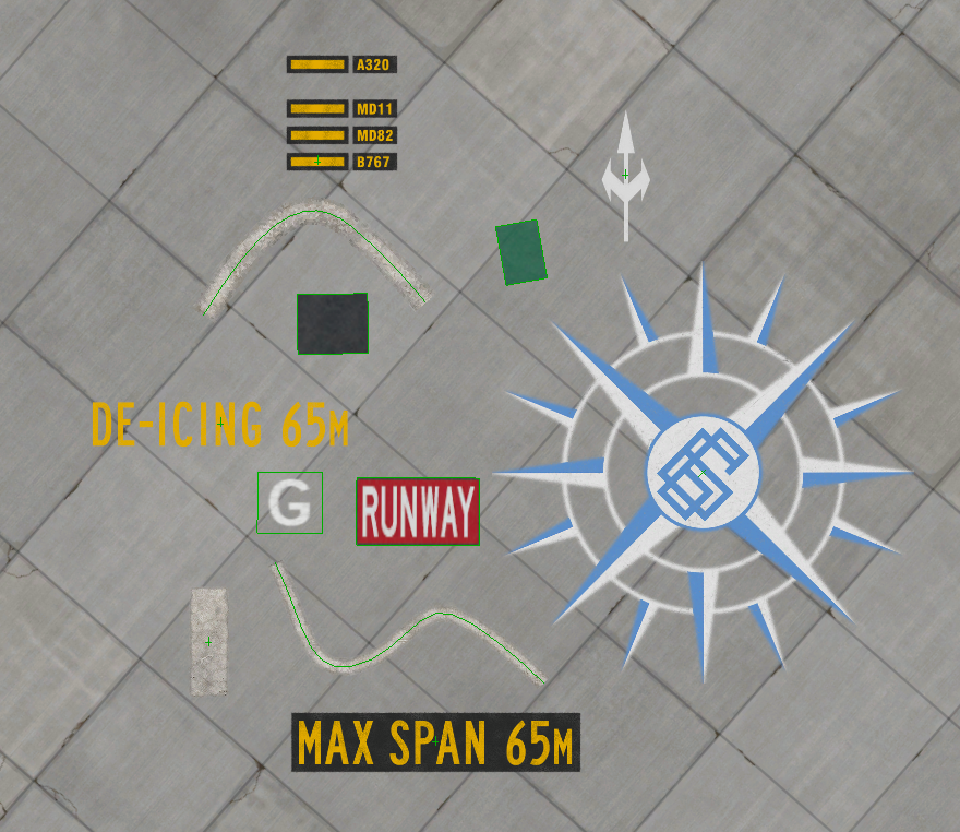
Ground Markings are ubiquitous around airports. They are all over the place and there are a wide variety of them. The image at right shows a sampling of ground markings that come with X-Plane. You can filter the Asset Browser by "markings" to see these types; however, generically using the term markings doesn't quite convey the whole story regarding "marks on the ground".
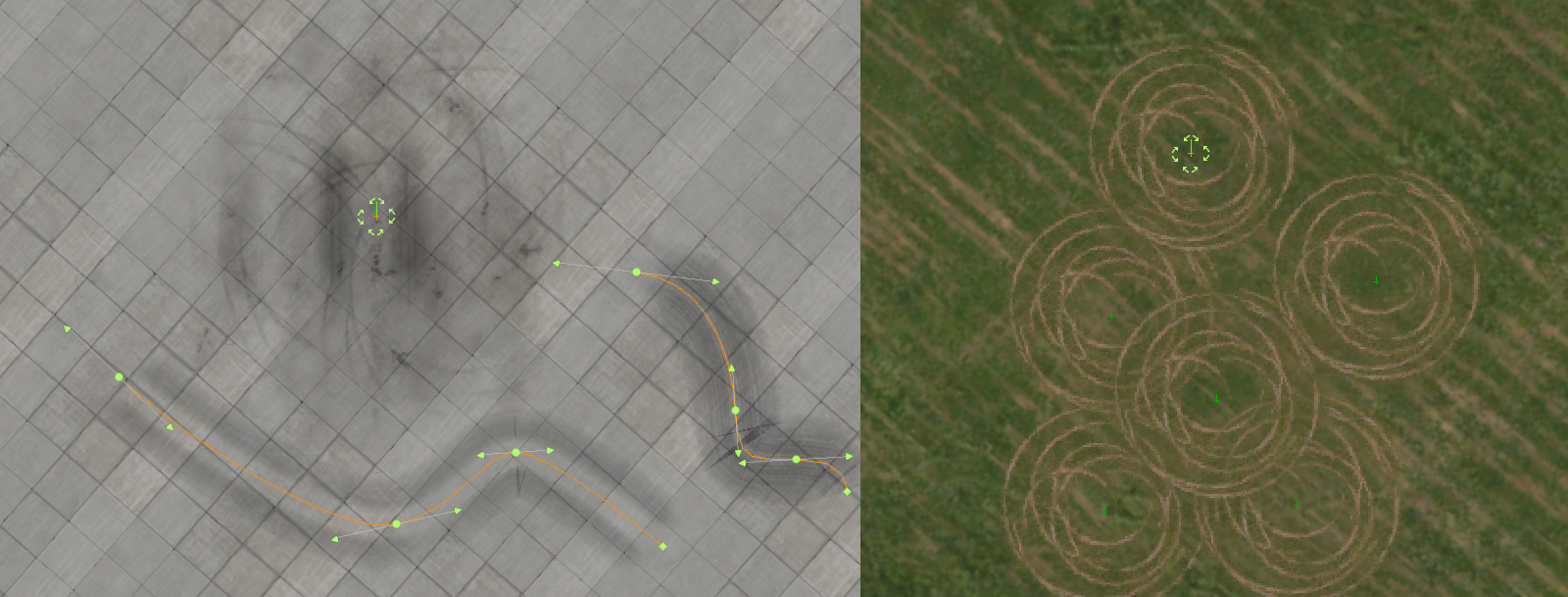
Most of the examples at right are examples of painted markings on the ground; however, we can also say that tire tracks or oil stains are marks on the ground, and we can also say that lawn mower tracks are marks on the ground/grass. The image below shows examples of these other types of non-painted markings, which are also included with x-Plane
Click to Enlarge
In both examples above, in the context of WED and X-Plane, these ground markings are simply artwork elements that are stacked on top of one another, and in WED, there are 3 Element types that can be used to create such Ground Markings and we'll discuss each further below.
- Draped Polygons (POLs - Polygon Tool)
- 3D Objects (OBJ - Object Tool) WITH embedded Draped Polygons (not all 3D objects have embedded draped polygons)
- LINE entities (LINs - Line Tool)
These entities that sit on the ground are generically called Draped entities because each are Draped on top of other geometry like a rug over flooring. If you have several of these draped entities on top of one another, then the order in which they are layered becomes important, lest some entities are covered up by others. This is where the concept of X-Plane's Draw Order becomes important, so we discuss this first.
Draw Order
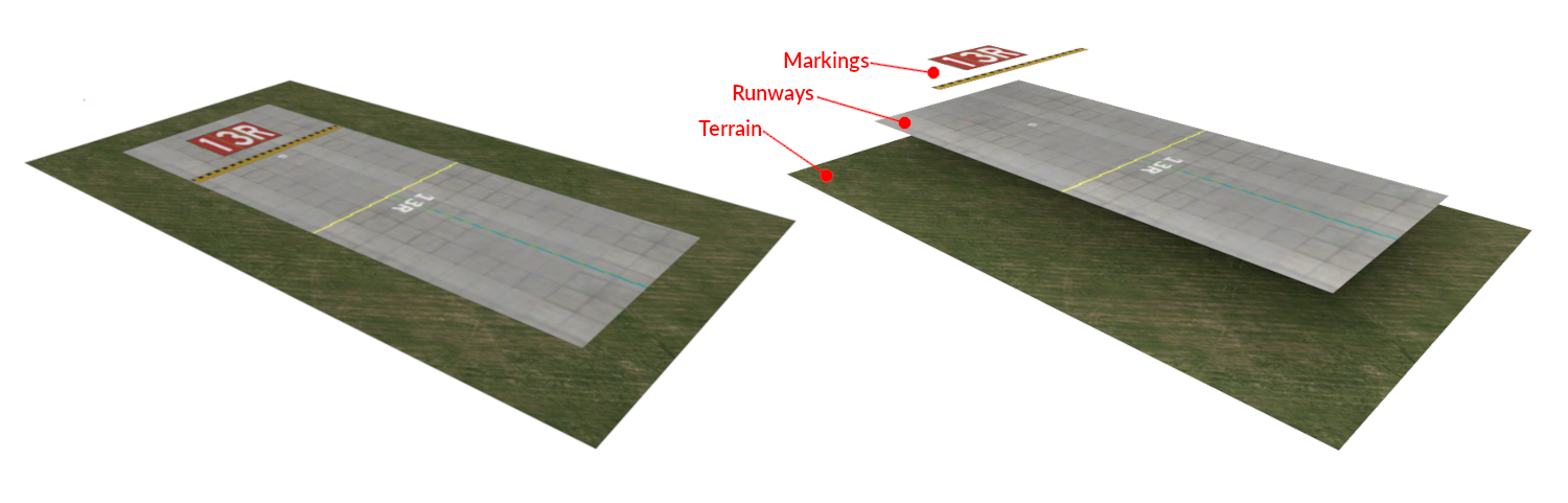
X-Plane renders the ground (and elements on top of it) by organizing scenery entities into layers and stacking them on top of one another. Because all these entities are essentially at the same level geometrically, X-Plane needs to know in what order to draw each entity. For example, you do not want the Terrain rendering after the Runway and covering it up. We need to render the Terrain first, then the runway, and then the markings on top of the runway, then any vehicles on top of the runway etc. The image below illustrates the concept.
Click to Enlarge
X-Plane has a very specific draw order and uses a Layer model to guide its rendering sequence. All of the default X-Plane art assets are already assigned to the proper layers so most will render correctly; however, there are some exceptions which are discussed further below. Additionally, if you develop your own custom art assets, then understanding X-Plane's draw order and layer model will become important.
There are 110 layers available to custom scenery authors, which is more than enough to stack scenery elements. Very rarely will you have more than perhaps a half-dozen elements on top of one another at most. These layers are called Layer Groups and are described next.
Layer Groups
X-Plane have the following named Layer Groups below, listed in their Stack order, with cars being on top and terrain being on the bottom. X-Plane's Draw Order is the inverse of the Stack Order, i.e. the terrain is rendered first, then the beaches, then airport elements, so on and so forth. As scenery authors, we are generally concerned with the stack order, i.e. "..what is on top of what".
cars [n]
light_objects [n]
objects [n]
roads [n]
airports [+n]
  -markings [n]
  -runways [n]
  -taxiways [n]
  -shoulders [n]
airports [-n]
beaches  [n]
terrain  [n]
You may note that the layer group airports is listed twice. The reason will become clear shortly. Recall in the previous section above we said that there are 110 layers available, which is obviously more than the short list above, so how does this work?
Each layer group is actually composed of 10 layers. So (11 named groups x 10 layers each = 110 layers total). These constituent layers are called offset layers and each named group have 5 positive offset layers and 5 negative. The layer group name and offset value are assigned to scenery entities via a LAYER_GROUP directive in the art asset files themselves which tells X-Plane when to draw the art asset.
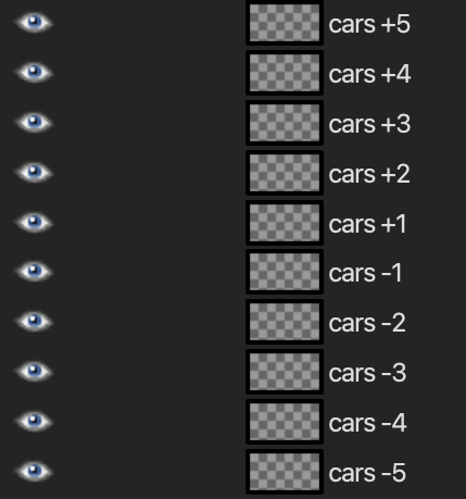
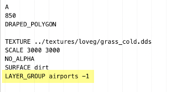
The image below left shows an example draped polygon (*.pol) file telling X-Plane to draw this asset in the Airports -1 layer group. If we think of these layers as stacked Photoshop® layers, then they would be arranged as shown in the image below right with anything on the cars +5 offset layer being above all the other layers for that named group. By assigning entities to specific layers in this way, you can control what entities are drawn on top of others.
Now, given that the named layer groups have a specific stacking order AND the offset layers also have a specific stacking order, the final stacked order of layers, from top to bottom is illustrated in the box below. Now is where we talk about WHY the airport layer group was listed twice in the above paragraph.
The airport layer group consists of 4 sub-groups, which is why they are indented in the above list. All the POSITIVE offset layers of the airport group will stack on top of ALL the airport sub-groups, and all the NEGATIVE airport offset layers will stack below ALL of the airport sub-groups. This order is illustrated in the listing below.
While it is possible to assign a layer group without an offset index, the result will be ambiguous, X-Plane expects an offset value. You should ALWAYS include an offset value after specifying the layer group name.
POL (Polygon) Markings
Draped Polygons can exist in two forms. One form is a Path-based area you create in WED that can be any shape you create, and the other form are 3D polygons embedded within a OBJ file (3D object). The OBJ based draped polygons are discussed in the next section, here we just discuss Polygons created with WEDs polygon tool, which are paths.
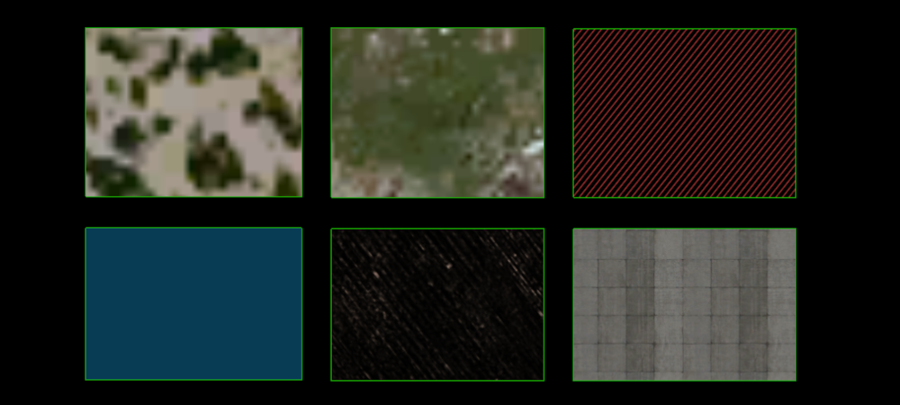
POLs are almost always repeating textures. The image below shows but a tiny sample of the 100s of patterns and textures available in WED. To get familiar with all the options, you should filter the Asset Browser for .pol and highlight each individually to see its preview. Note that while all the example POL paths below are rectangles, they can be any path shape you create.
Some of the POL styles will render on top of others as they're assigned layer_group dictates. For example, the bottom-middle are "lawn marks", intended to be overlaid on grass and would render on top of any POLs created with a grass/lawn texture. The top-right polygon is a Safety Area that would render on top of any pavement POLs etc. If you are creating your own custom POL file definitions and textures that are designed to be overlaid with one another, you too will have to assign the proper layer group and offset value as described above in your POL files to ensure they stack as you desire.
Click to Enlarge
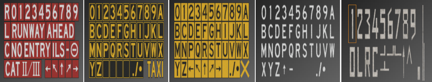
Recall we just said that POLs are ALMOST always repeating textures? There is a small exception, which we call a Texture Atlas, and there are not very many of them in WED, only the five shown below, but since they are defined via a POL file, created with the Polygon tool, and would show up if you filtered the asset browser for .pol, we mention them here because there is a special way of working with these.
Texture atlases are handy when you have a finite amount of pieces that may be combined in a lot of differing ways. For example, given just 10 elements, you can create 1023 differing combinations of those elements. Clearly 1 texture atlas is easier and more efficient than creating 1023 individual pieces. A typewriter keyboard is a form of "character atlas"
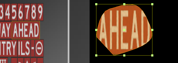
Click to Enlarge (Texture Atlas POLs)
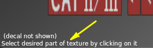
Whenever you select one of these Texture Atlas POLs, you will see a message in the lower left corner of the preview window, prompting you to select a part of the texture. Only texture atlas types will have this message. In the image above, the right-most texture have the numeral 1 selected, which is indicated by a highlighted bounding box.
With a portion of the texture selected (and the Polygon Tool selected), you then create a closed path and WED will fill in that area with that portion of the texture you selected. Now because paths can be any shape, but the selected element itself is clearly rectangular, then what happens if you create a non-rectangular path? The answer is illustrated below. The bounding box of the path matches the selection rectangle, and the path within determines what part of that is shown.
Since all these atlas based ground markings are generally rectangular, then the proper way to create them with the Polygon tool are to only use four vertices with no curved segments. Furthermore, the first vertex you create should be the upper left corner of your marking, otherwise your texture will be rotated. The nominal way to create these are to create the sign Right Side up and then use the marquee tool to rotate it after. This technique is illustrated in the clip below.
You may note that the path above is not very rectangular, but more trapezoidal. Fortunately, WED have a convenient menu command, Edit > Orthogonalize, which will automatically rearrange the vertices of the selected path such that all the corners are 90º. Once you have 90º corners, you can use the Marquee Tool to scale and rotate the marking to its final size as illustrated below. In the example clip below, the orthogonalize command was executed twice, again after the stretching operation.
OBJ Based Markings
Click to Enlarge
OBJs are normally non-flat 3D objects that sit on top of the ground, like a house, a car, water-tower or a building; however, they may optionally contain polygons that are designated as Draped and X-Plane will push these polygons down to lie flat against the ground. Conversely, you can have an OBJ that ONLY have draped polygons in it, and this is what we mean by an OBJ Based Marking described in this section.
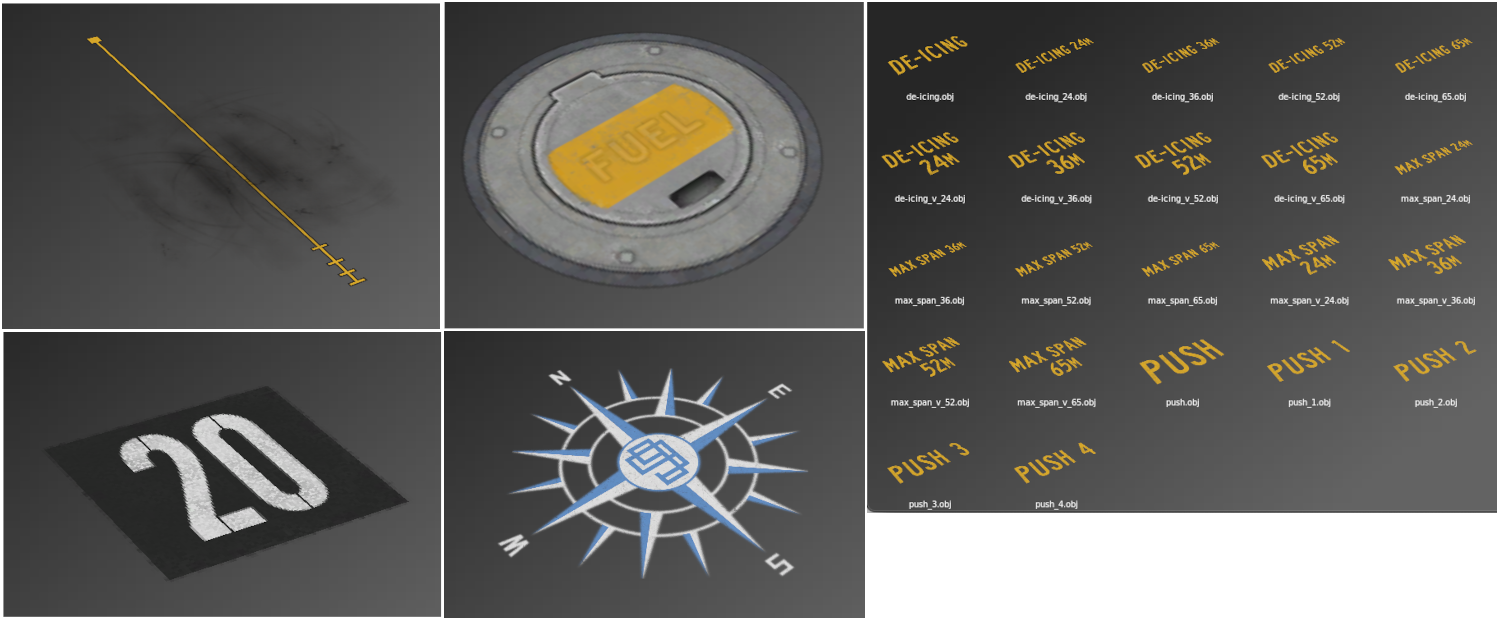
Markings are suitable to be draped polygons within an OBJ rather than a texture atlasa when the marking itself is a fixed size that will not change. You cannot stretch OBJs in WED, only move them around and rotate them. You can think of OBJ based markings as fixed size "stamps" or "decals" on the ground. The image at right shows a small sampling of some OBJ based markings in WED.
Because these are OBJs, you place them with the Object Tool. You can filter the Asset Browser by .obj, however, you will get all OBJs, whether they contain draped polygons or not. WED does not distinguish between OBJs that do or do not have draped polygons within them. You will simply have to look at them in the preview window to see if they are flat markings or not.
LIN Based Markings
LINs are line based ground markings. These are markings that are repeated along the length of the line. The line in this case means an open path in WED. WED have literally 100s of LIN styles to choose from and the best way to become familiar with them is to filter the Asset Browser for .lin and look at their preview and experiment by creating them in the map view.
When you select a lin type resource in the Asset Browser, WED will select the line tool for you. We make special mention here that LIN assets should NOT be used for taxiway lines. See the Lines Tool section of the manual for more information on when to use LINs versus taxi-line ground markings.