Road Editing
WARNING
The Roads Tool is not for creating large roads networks or complex intersections/overpasses, but rather is intended for minor reshaping of existing X-Plane road segments, and/or the creation of smaller stretches of custom/feeder roads, which may or may not connect to X-Plane's existing Road network. To edit roads successfully, make sure you are comfortable with the Path Editing techniques in WED.
General
Roads in X-Plane are special open path bezier entities that X-Plane may automatically animate vehicles upon. As a scenery author, you can only specify the type and path of your roads; however, you cannot specify the nature of the animated vehicles on those roads. X-Plane may not animate cars on short road segments or smaller/more narrow road widths.
Creating and Editing Roads in WED is a special activity, not frequently done except for the most customized scenery. X-Plane creates its existing roads from Open Source Data, which may not include smaller roads that service businesses, private roads or roads within a gated property. Another characteristic of default X-Plane roads is that they only consist of straight segments, simply because the source data Laminar uses only have straight segments. Default road segments may be made curved in WED, but it is a manual "per segment" authoring activity.
X-Plane's default roads are hard baked into X-Plane's scenery DSF files and are updated infrequently with major releases of X-Plane. As such, new real roads may be built that are not in X-Plane and you can create these manually with the Roads Tool.
Road Anatomy
Creating/editing roads successfully in X-Plane is mostly about understanding the anatomy and limitations of roads in WED, as well as knowing how to edit paths. Make sure you fully understand bezier path editing before working with road entities, particularly how to add/delete bezier control handles.
First thing, we get familiar with the type of nodes that make up the road paths:
-
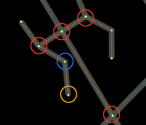
"Intersection Node" means a node where at least three segments emanate from the node. The image at right illustrates these types with red circles. These are also called Shared or Junction nodes.
-
"Interior Node" means a node that ALWAYS have only two segments emanating from it. They are called interior nodes because they are "in the interior" of the path, NOT an intersection type, and not on an end. (Blue Circle at right)
-
"End/Termination" node means a node which only have one segment emanating from them. (Yellow Circle at right), i.e its "on the end of the path"
Familiarization with these types becomes relevant when you want to create curved road segments. If you only create straight road segments, ala "connect the dots style, then knowing these node types is not important.
We begin with some generic statements regarding road path characteristics you will want to keep in mind if you are going to edit/create roads. Some of these points may not make sense now, but will as you read further below and work with roads in WED.
- Roads are a network of paths where all intersections consist of one node that is shared among all the paths coming into that intersection node.
- Only endpoints of paths can be at path intersections and shared. An Interior Node on a path cannot be part of an intersection.
- A single path usually consists of all the segments between intersections, but do not have to be. A single straight road between intersections could be made from one straight path with only two endpoints, or from one path with multiple interior nodes, OR it can made from multiple straight paths lined up with shared endpoints. They would all look the same in WED. The only way to positively identify a path and its member nodes is to select a road segment in the map view with the Vertex Tool, which will select the entire path and its member nodes. The road network shown in the image above contains 11 separate paths, some with one segment, some with more.
- A path may not be split between its endpoints. Interior points may be added/deleted though.
- A Road style (4-lane, 2-lane, dirt-road) is configured per path.
- An intersection/end node shared with multiple paths only shares is location, not its bezier curvature (see video next section)
- The end nodes of a path only have one bezier control handle for curvature. If you have two connected,curved paths that share their end nodes, and desire path tangency across the junction, you will have to set the bezier handles of each curve independently for the end points. (again, see video clip next section).
- There is no logical hierarchy between road paths and their member nodes shown in the hierarchy panel. Do not try to understand the hierarchy panel entries with regards to roads. Best practice is to create a group to contain your road work and pay no attention to the elements inside it. Do all your editing graphically.
- X-Plane will auto-generate plausible intersections for simple road styles and simple intersections only. Do not expect X-Plane to generate complicated overpasses or interchanges for highways.
Coincident / Shared Nodes
Coincident nodes are two or more nodes that are exactly on top of one another in the WED map view, and APPEAR as a single node. Coincident road nodes are not allowed and if you try to export out your scenery with these, then WED will give you an error message, "Error: Double Road Junction. These should be merged".
Default X-Plane roads have no coincident nodes, you will only encounter these if you create your own roads and place an end node at an intersection and forget to merge the overlapping nodes after. Whether you connect an end node to default road nodes or custom roads you created previously does not matter.
Whenever you place a road node over any other road node to connect segments, you must select all the coincident nodes and merge them so that the new single node becomes shared with all the segments emanating from it. If you use the vertex tool to select an Intersection node with a single click and move it around, all the segments emanating from it should move also. (see video clip below)
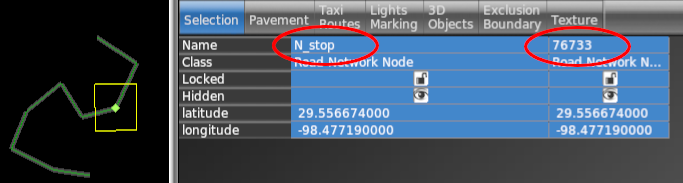
You can identify coincident nodes by using the Vertex tool to drag a bounding rectangle around the nodes and if you see more then one column in the attributes panel as shown at right, then you have selected multiple nodes. Best practice is to merge the nodes immediately after you place/snap a node to an existing one.
To merge coincident nodes, use the Vertex tool to draw a bounding box around the nodes, and use the Edit > Merge command (SHIFT - Commmand - M) to merge the nodes into a single node. With the single node still selected after the merge, you should now only see one column in the attributes panel, indicating only one node selected.
As mentioned above, shared nodes only share their location with their connected paths and nothing more. Each path sharing the node is its own path and edited independently. The video at left illustrates how moving a shared node affects all connected paths, but you have to edit bezier handles for each path's end points separately. This is why you have to select the segment to edit a bezier handle and cannot just select the shared node, because WED would not which segment you want to edit. WED will only show you bezier handles on a selected vertex if it knows exactly which segment to affect. With intersections that share nodes, that is ambiguous until you select a specific segment.
Creating Curved Roads
In the real world, a LOT of roads are curved and if you are going to edit roads, then there is a good chance you will want to make a lot of them properly curved as they are in the real world. Because roads are paths, creating curved roads is simply a matter of configuring the road paths bezier handles on the nodes, which is why you need to be familiar with path editing and managing bezier handles.
The only caveat when creating curves on roads paths versus other path types, is that roads have intersections with shared nodes. This means when creating curved segments emanating from intersections, you have to select the segment you want to edit first and then you can adjust the bezier handle for that node. This is illustrated in the video clip above. For interior nodes that only belong to one path, you can edit those bezier handles exactly the same as you do for any other path type.
Importing Roads into WED
Importing autogen roads into WED is relatively straightforward. Two things are required.
- A selected Exclusion entity (poly or rectangle)
- That selected exclusion entity must be configured to exclude roads.
With the two above criteria met at minimum, you then execute the menu command: File > Import Roads (+ Autogen), which will then import only those road paths that have vertices located within your exclusion zone. If your selected exclusion zone is not set to exclude roads, then the menu item to import roads will be grayed out.
The road importer will create a new group in the hierarchy panel each time you run that import command. The name of the new group will be the path to the DSF file from which the roads were imported from. Inside that containing group will be a subgroup called Roads which will contain all the actual road pieces. The entities inside this Roads group are quite unintuitive and its generally not necessary to have to worry about anything inside the Roads group. Just close that group and do all your road editing graphically.
Road Path Attributes
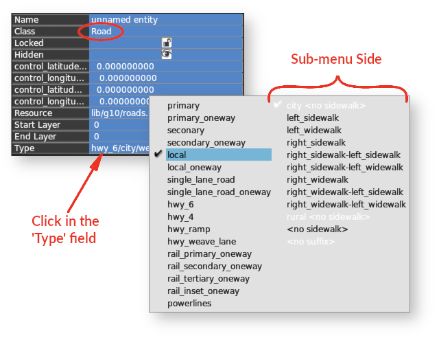
Whenever you select any road segment, then the entire path will be selected. The Class Attribute for the selected path will be Class = Road as shown at right, and this is where you may configure the style of the road.
If you click in the Type field, then a pop-up selection menu will be shown. The Roads pop-up menu is slightly differing from other pop-up menus like Taxilines or Airport Lights, in that the right side of the menu is actually an "options" sub-menu to the left side. In other words, you select a road type on the left side, and then enable an option on the right side. Only one option per road type is available. Option items listed in white text are not available for the selected road style, only those shown in black text. You may select the options in white, but they won't do anything. The available options will change depending on which road style you select on the left side.
Reversing Road Segments
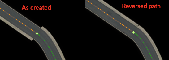
Because road paths can have asymmetrical configurations, like a sidewalk on one side, then its possible to have two adjoining road paths where the asymmetrical feature is on opposing sides. In these cases, you can select one of the paths and reverse its direction, which will move the feature to the opposite side. You can reverse a paths direction by selecting the path and executing the menu command, Edit > Reverse . The image at left shows the before/after when using this command.