Terminal Kit
General Overview
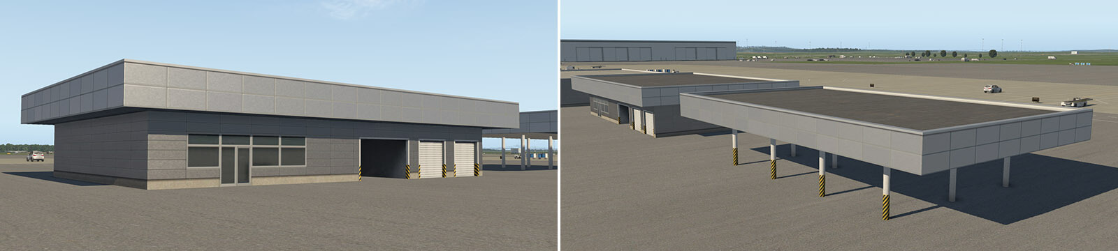
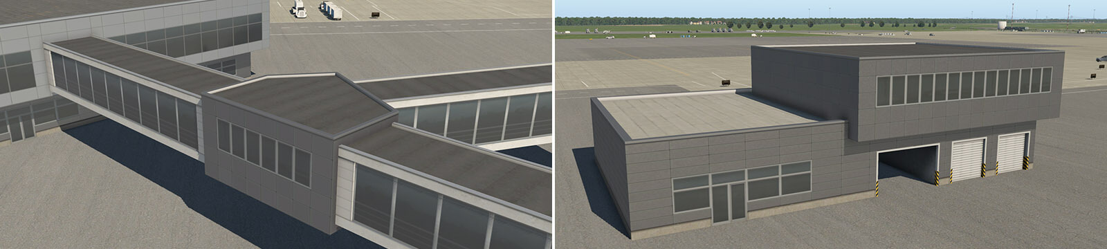
Terminal Kit simply refers to a collection of Laminar Library facades and OBJs in WED that are specifically targeted at creating modern airport terminals, i.e. *"Great Halls", multiple levels, pedestrian bridges, roof equipment, etc.
Whereas the original facades for terminals were created with a single facade path and locked you into pre-configured fixed-height designs, the Terminal Kit pieces, in contrast, are more low-level components intended to be stacked, overlapped and combined in various ways to create a wider variety of multi-level building configurations.
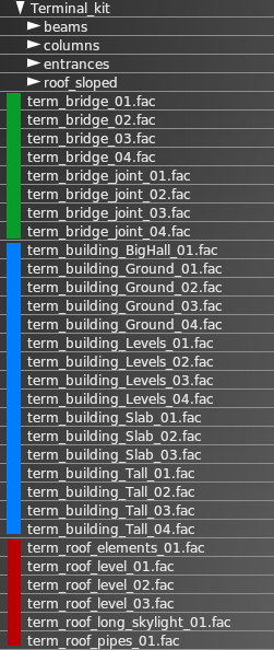
All the pieces that come with "the kit" are designed to work together and are completely modular. The Terminal Kit component list in WED are shown at right and can be found in the Laminar Library Asset Browser in WED at the following path:
lib/airport/Modern_Airports/Terminal_kit
The basic concept is to utilize differing facades and OBJs for differing architectural parts of the building. For example, one facade is used for the ground floor structure, and another facade would be used for the floor levels above, and yet others for structures on top of roofs. This approach requires a bit more work, having to overlap multiple facade paths, OBJs, Strings and keep track of it all; however, this method also offers far greater design possibilities and allows you to create much more plausible airport terminals.
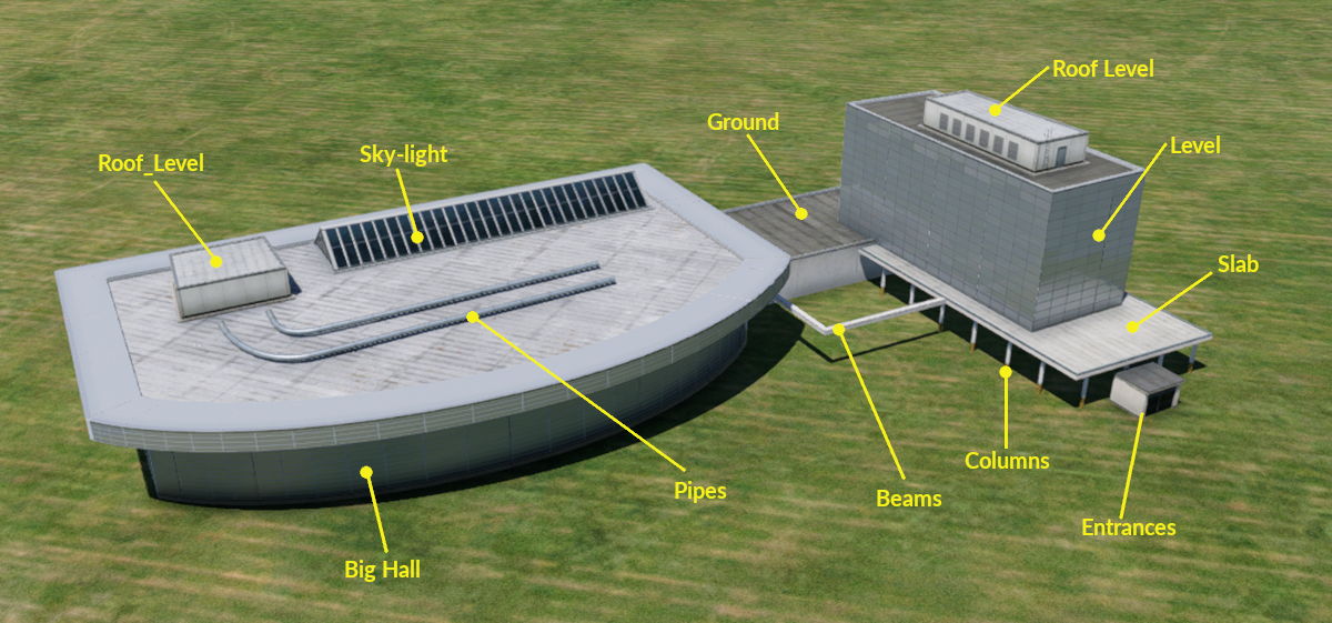
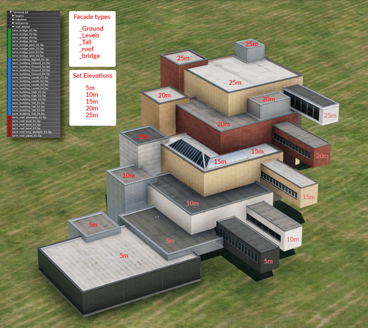
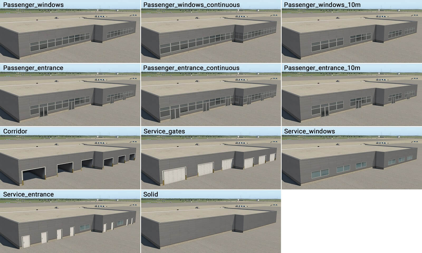
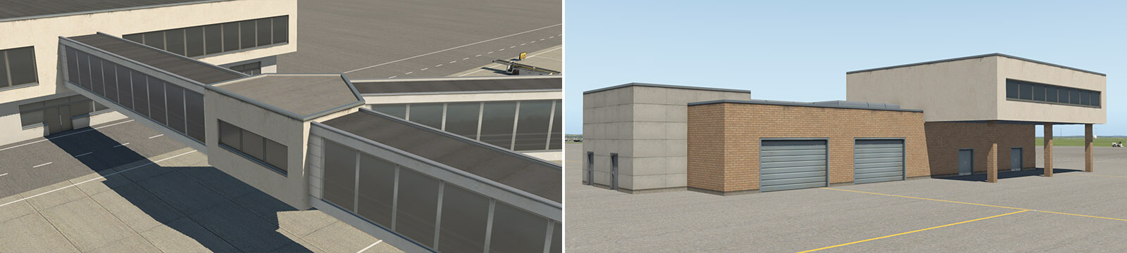
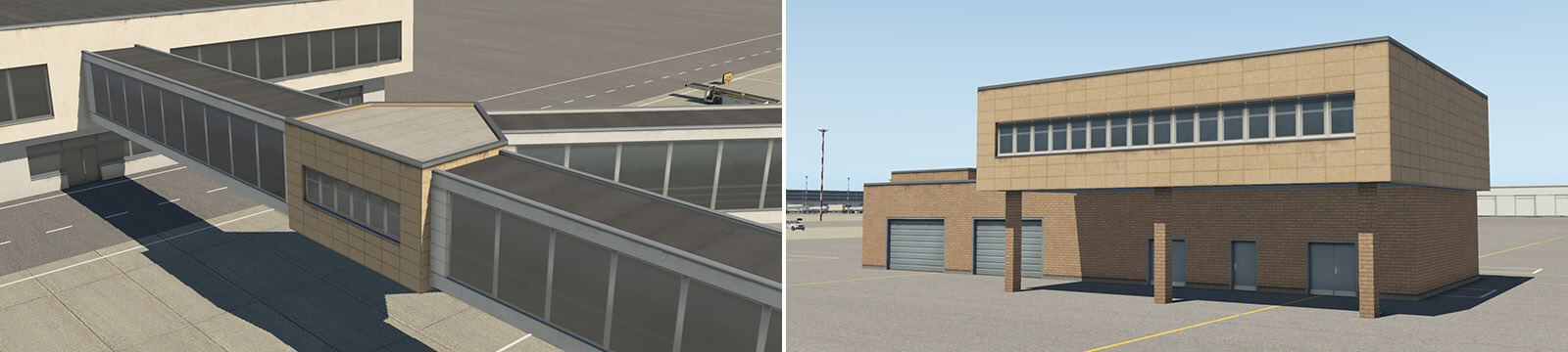
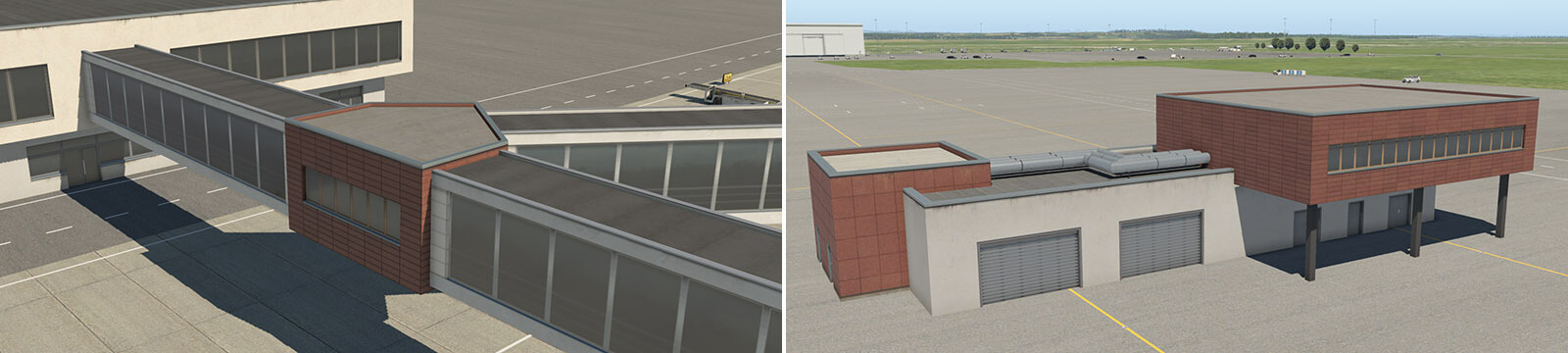
The components can loosely be divided into two categories. BASE elements and ACCESSORY elements. The Base elements constitute the foundational "mass" of main structures. The Accessories are those things that are "tacked on" to the main structures after. You can see the Accessory groups in the image at right, Beams / Columns / Entrances / Roof_Sloped.
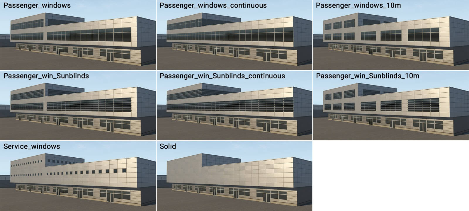
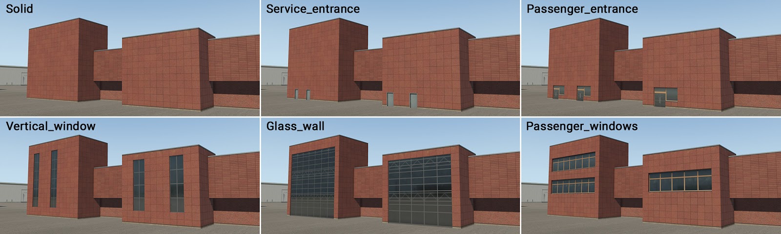
The BASE components of the Terminal Kit are prefixed with “ term_” so you can easily filter for them in the WED library hierarchy. The BASE terminal pieces are further divided into three sub-groups, each representing a logical vertical level of a structure.
| term_building_ | .. for construction of the main buildings |
| term_bridge_ | .. for construction of connecting bridges |
| term_roof_ | .. for construction of the roofing options |
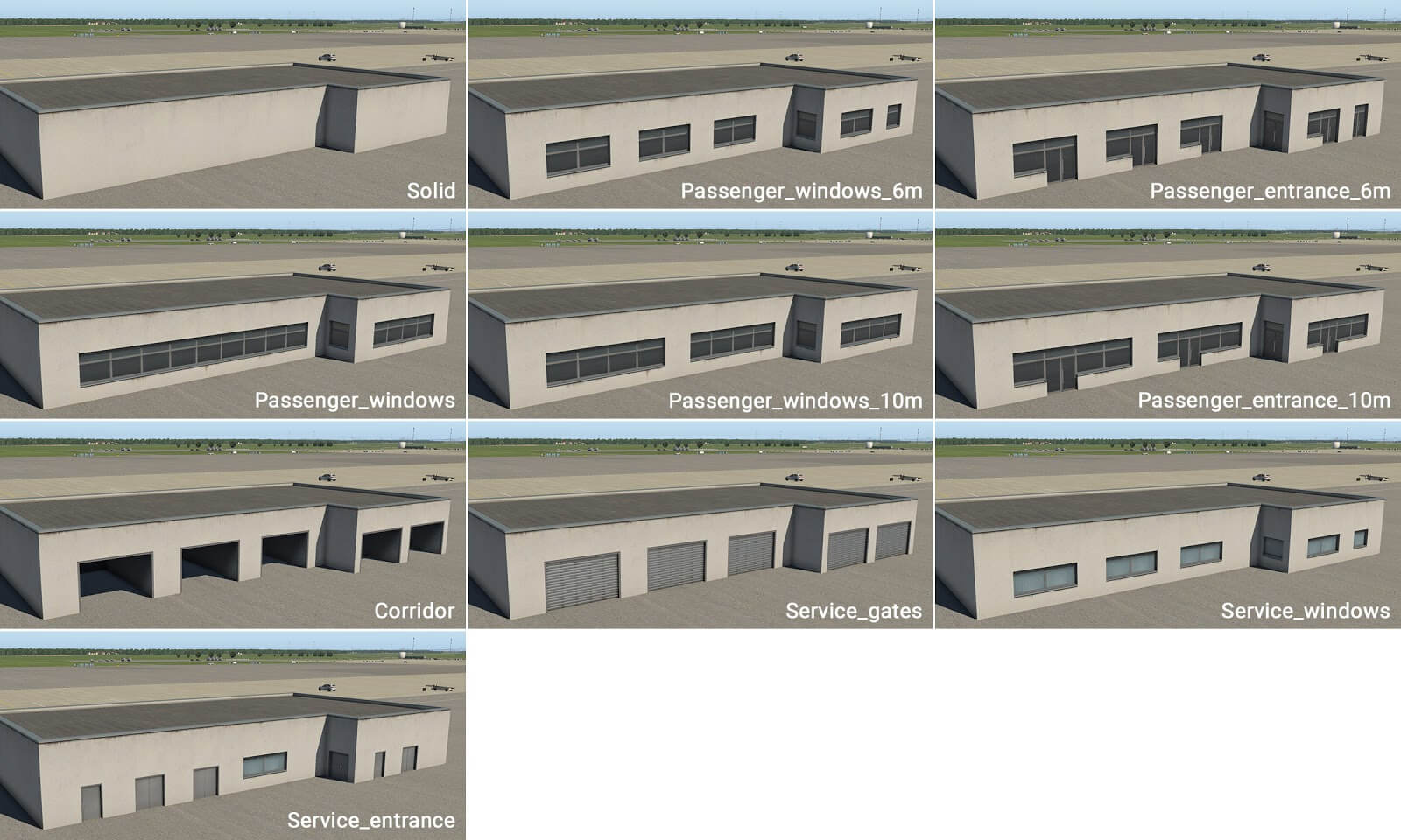
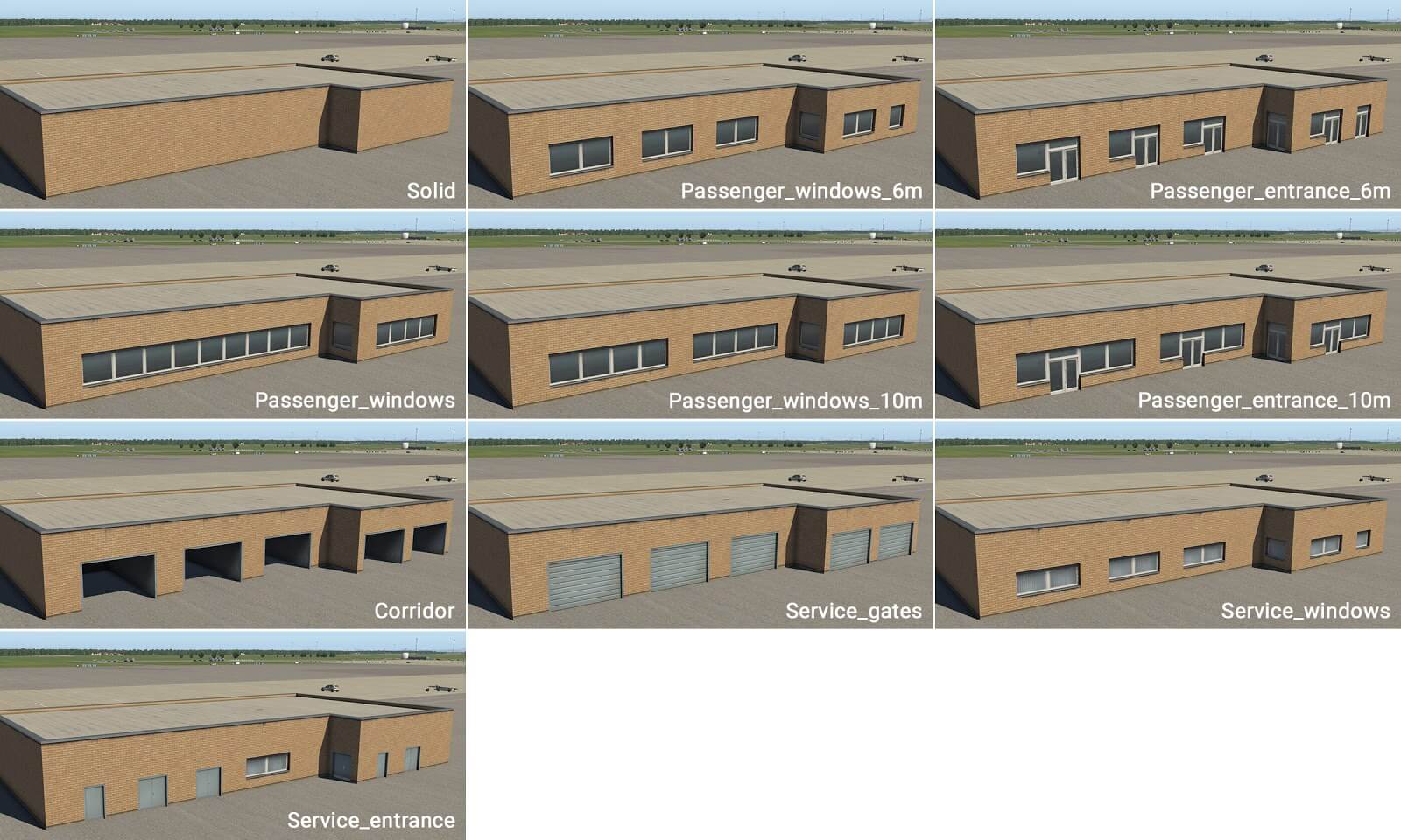
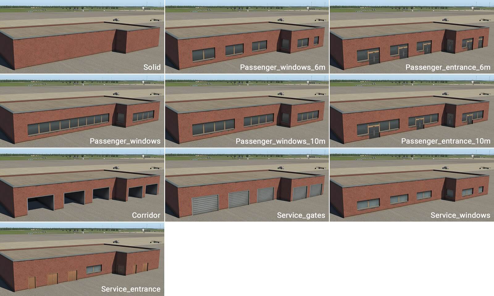
The term_buildings_ base sub-group above are generally the first elements you create and have the following 4 types of "buildings" available.
| term_building_BigHall | .. for central HUB structures that terminals emanate from, i.e. "Food Courts", "Big Glass Walls" |
| term_building_Ground_ | .. for single-level structures that actually sit on the ground. |
| term_building_Levels | .. for building levels 2-5 stories high (5m per story). NO ground level. These begin at 5m off the ground. |
| term_building_Tall | .. for the highest roof structures. Always a "tiny bit taller" than an equivalent Level. (see Example Stacking section below) |
The available ACCESORIES to complement the base structures and add detail are as follows:
| term_roof_elements_ | .. HVAC equipment, vents, and misc |
| term_roof_level_ | .. Smaller enclosed structures that sit on Roofs, i.e. Roof access stairwells or enclosed HVAC equipment. |
| term_roof_long_skylight_ | .. for "linear" skylights on roofs, i.e. pyramid or barrel shapes. |
| term_roof_pipes | .. for pipes on the roof, i.e. HVAC water systems. |
Click to Enlarge
The image at right showcases how these differing elements can work together to create more complex structures. In order to stack these elements predictably, we need to fully understand how these pre-configured facade pieces are aligned vertically. We discuss how these pieces are stacked and aligned next.
Element Stacking
The following sections discuss the various elements and height/elevation considerations when configuring their height Attributes. Further below is an interactive image where you can hover over the various elements to see the height relationships between entity types.
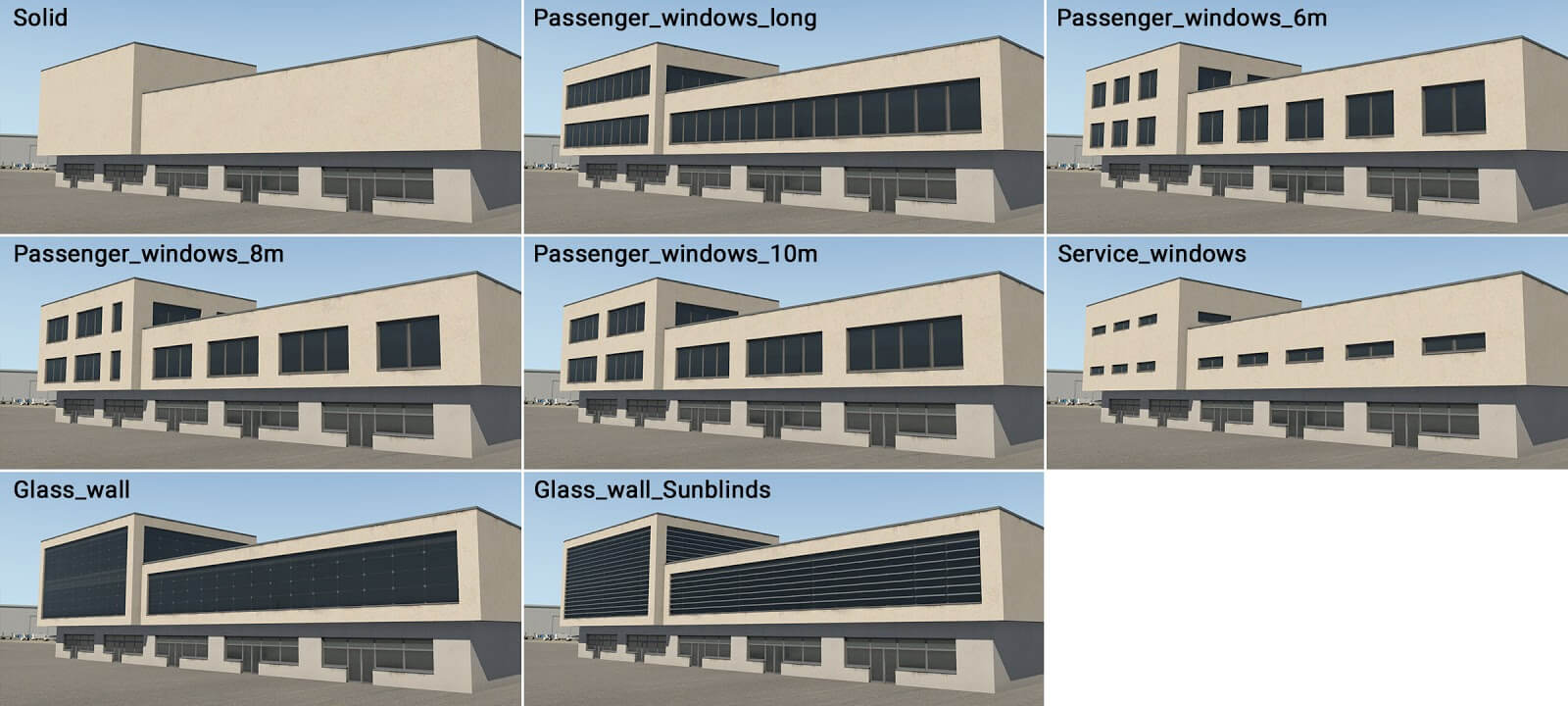
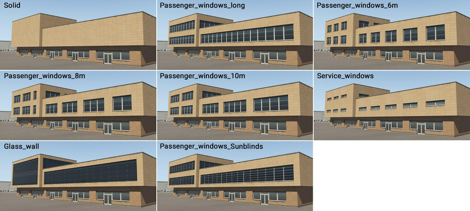
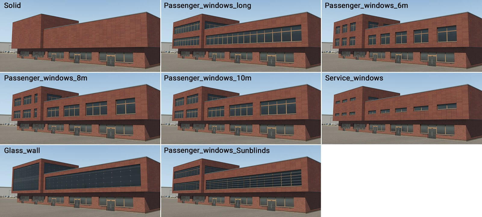
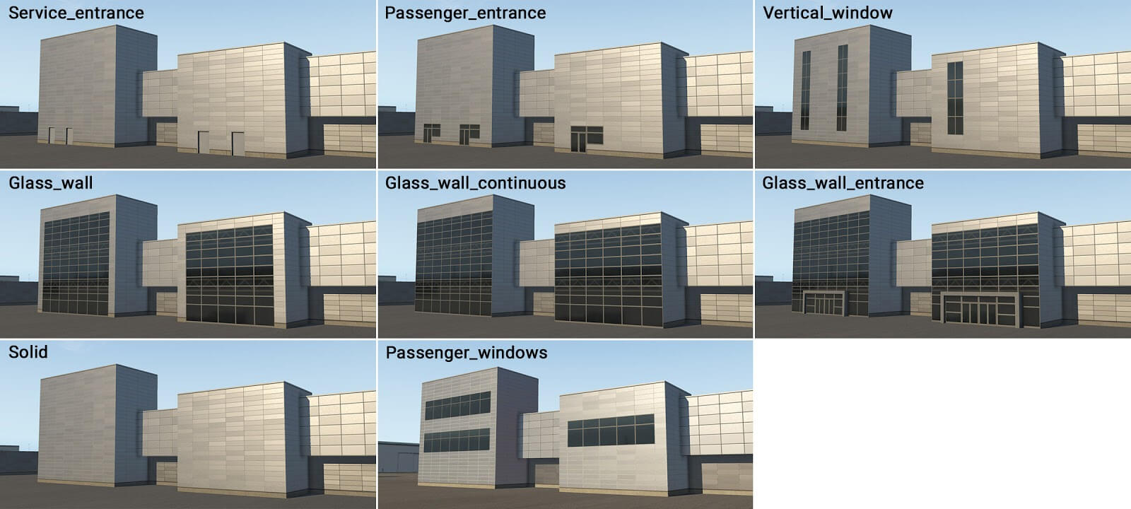
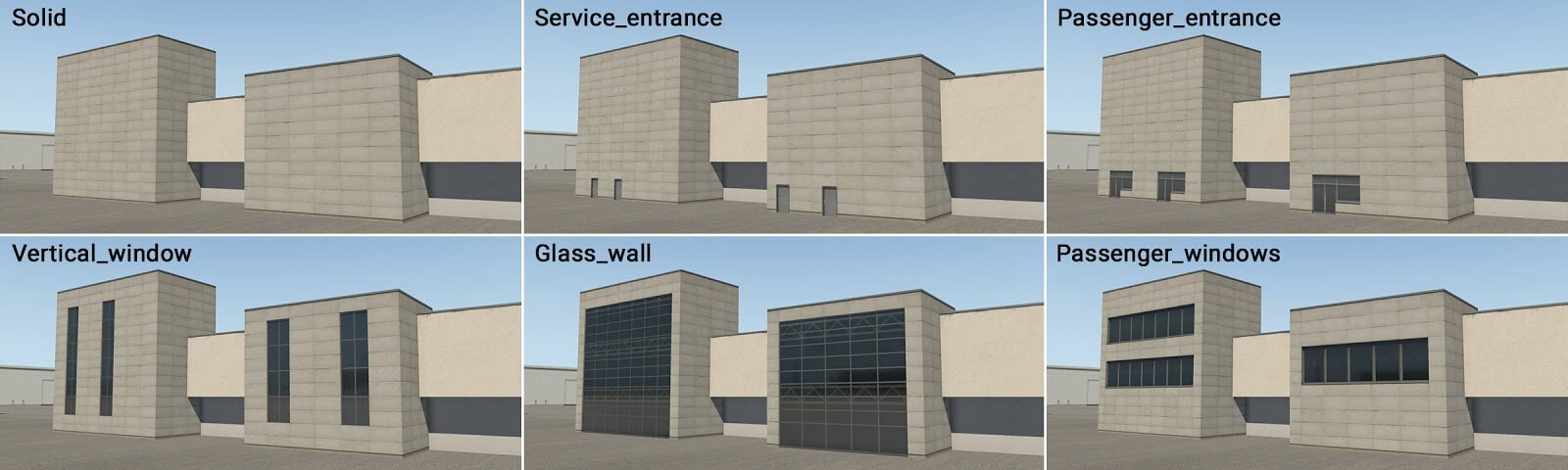
Ground Facades
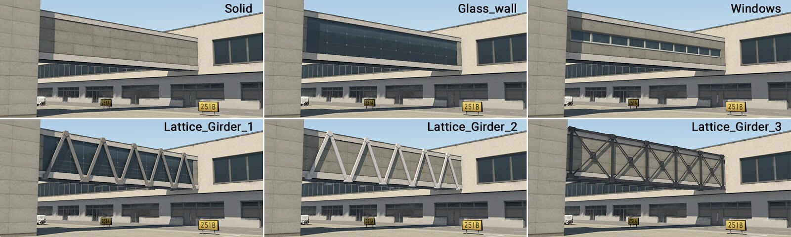
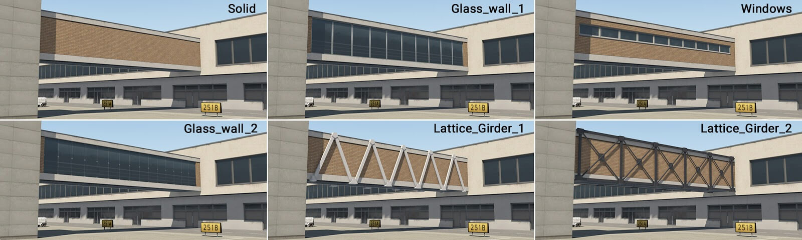
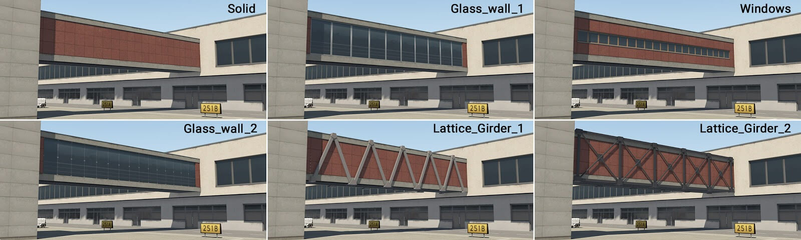
Ground facades always sit on the ground and their roof heights are fixed at 5m. Because they're on the ground, these facades support Door/Entrance wall segments, as well as windows.
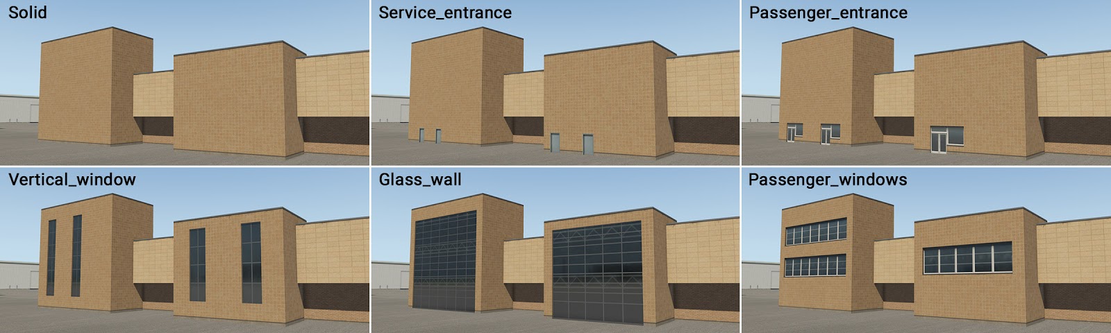
Levels Facades
Levels facades do NOT sit on the ground, and begin at 5m above the ground. They are designed to be intermediate levels with NO doorway wall segments available, only windows and solid walls. The ACTUAL available roof heights of these facades are: 6m, 9m, 14m, 19m and 24m, so their roofs heights sit JUST below the Tall Facade roof heights described above. This allows for staggered roof offsets of adjacent structures. This offset can be seen in the image below.
Tall Facades
Tall Facades are the most predictable height wise. They sit on the ground and their roof heights are in multiples of 5m, from 5m to 25m max. Being on the ground also, these support Doors/Entrance wall segments also. These have various purposes: volume extensions, stair-towers and other vertical parts. It is slightly higher (by units of 1 meter) than adjacent Levels modules, and can be inserted into other basic modules, or used as a stand-alone module.
Bridge Facades
Bridge facades clearly do not sit on the ground and only support window and solid wall segment types. Their height attribute configures how high they are above the ground. 5 differing heights are available
Roof_Level Facades
Roof level facades are used to create enclosed maintenance or roof access style structures that sit on top of roofs. These are essentially 1 story "mini buildings" that sit on top of a roof. They are appropriate to use on top of Ground facades, and Levels facades > 10m. They are not used on top of the Tall facades.
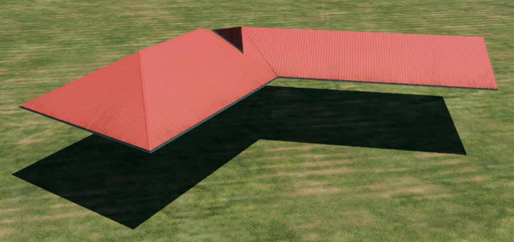
Sloped Roof Facades
Click to Enlarge
Sloped Roof facades are linear elements and create simple hip & gable roofs. Several widths are available, and their available heights are 5m, 10m, 14m, 19m and 24m. These roofs are used on top of ground and levels facades, but not on top of tall types. These types of roofs may be found on smaller terminals.
Example Stacking
NOTE
When you set a height attribute for a facade in WED, then X-Plane will select the pre-built facade piece that have the closest roof height to your specified height. Facade roof heights are NOT dynamically set to an exact value. This is why you can set multiple entities to a roof height of 25m and some pieces will have offset roofs, because they are designed that way.
The spirit of the terminal kit is to allow you to mostly specify heights in multiples of 5m and just have them align. If you have an entity that is not as expected height wise, then you can simply add or subtract a meter or two to the height as needed to get X-Plane to select the next highest/lowest level piece. The Facade Preview; however, will tell you the EXACT heights the facade is designed for.
Hover over the image below to see the relationship between WED pieces and their heights!
Useful hints
-
This Terminal Facade kit comprises basic modules of 2-meters in horizontal length. This means that a single metal panel is two meters long. There is no explicit reason to be aware of this, except that it may prove useful when positioning manually placed assets (eg entrances and columns) adjacent to the terminal modules themselves.
-
All roof textures have some kind of directionality (appearing as ‘strips’). This is always perpendicular to the FIRST segment of the polygon (the white line in WED). You can rotate segments in WED by pressing Ctrl+R. This is important (especially with bridges) whereby the first segment should be oriented in the direction of the bridge axis.
-
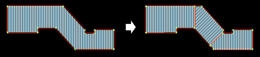
Large terminal buildings often have a very complex footprint. Don’t attempt to replicate this complex shape with just a single facade polygon. It’s much better to divide the structure into smaller logical shapes. This also helps when dealing with roof directionality, and where there are large differences in terrain elevation at the extreme ends of the building. REMEMBER: You can split a closed path by selecting TWO non-adjacent vertices and using the Split command to slice between those verticies!
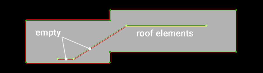
At times, the terrain may have a significant gradient. This may cause roof elements to ‘float’ above the module below, or sink into it. This is because modules are rendered at the exact height of the center of the first polygon segment. To control for this, some roof modules have an “empty” wall. The artist may start the module chain with an “empty” segment, near the center of the first segment of the underlying module. The artist then draws the second empty segment in the desired location of the (visible) roof element, and this should render at the correct height.
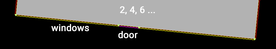
When an artist requires doors, gates or corridors at exact locations in a long module wall, this may be accomplished by the insertion of a node, and a change in wall-type (even in straight segments). Keep in mind that basic modules are 2 meters in length, so try to use segments that are approximately 2, 4, 6 or 8 meters long. This helps avoid unwanted stretching.
The height of one metal panel isn’t technically one meter, but actually 96 centimeters. The reason for this is related to jetways, but not important to artists when constructing the terminal modules. Likewise, the exact height of floors are actually 4.6 m, 9.4 m, 14.2 m, 19 m and 23.8 m.
Ground Components
term_building_Ground_01.fac
term_building_Ground_02.fac
term_building_Ground_03.fac
term_building_Ground_04.fac
Level Components
term_building_Levels_01.fac
term_building_Levels_02.fac
term_building_Levels_03.fac
term_building_Levels_04.fac
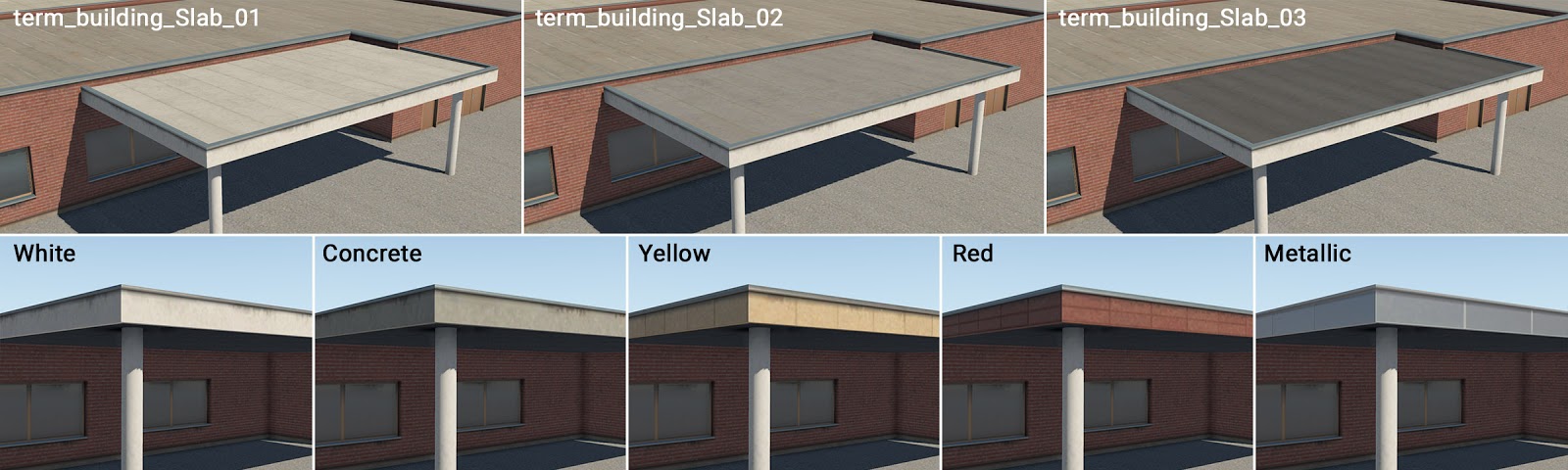
NOTE
When the height of these Level facade types are set to 7m or less, they then render as a ‘slab’ regardless of which wall type is selected. This can act as a flat roof for columns or may be used above ground facades. The image below shows examples of this special use of these facades.
Tall Components
term_building_Tall_01.fac
term_building_Tall_02.fac
term_building_Tall_03.fac
term_building_Tall_04.fac
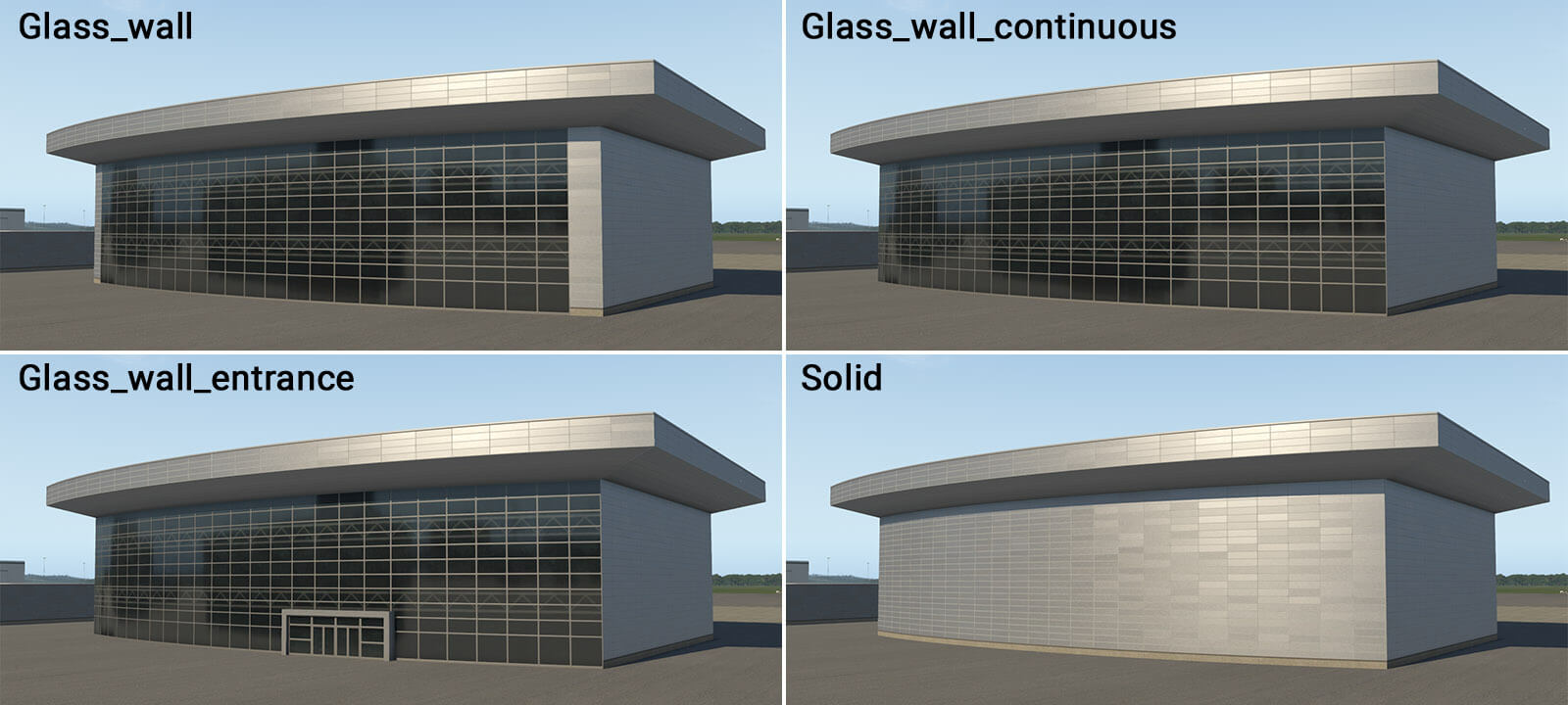
Big Hall
term_building_BigHall_01.fac
NOTE
This is special module for the creation of large halls with glass walls. It is intended for simple shapes like rectangles, and can’t handle negative corners (concave angles).
Slab
term_building_Slab_01-03.fac
Bridges and Joints
term_bridge_01.fac
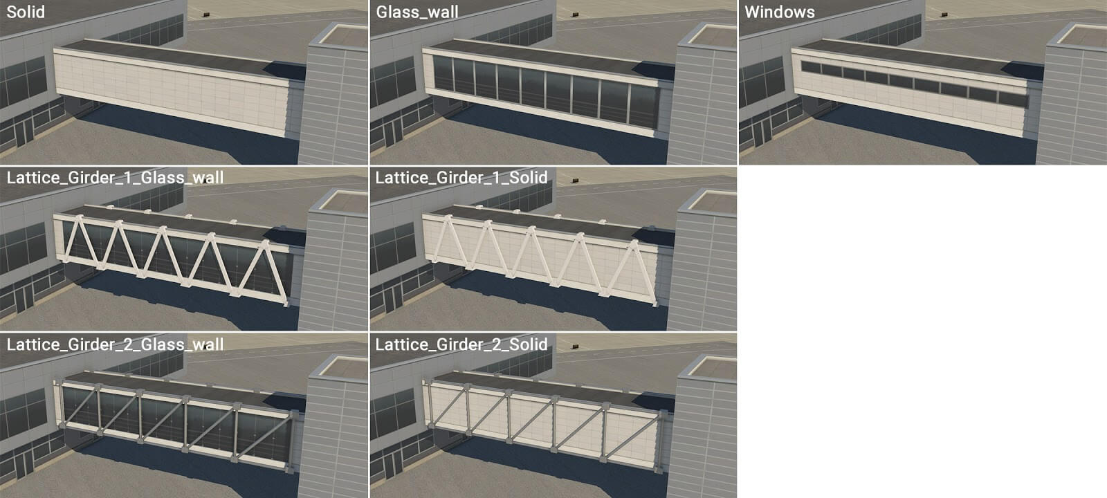
term_bridge_02.fac
term_bridge_03.fac
term_bridge_04.fac
term_bridge_joint_01.fac
term_bridge_joint_02.fac
term_bridge_joint_03.fac
term_bridge_joint_04.fac
Roof Facades
NOTE
Normally you set the desired Roof Height of a facade. For these types, you set the roof height you want these to sit UPON. Therefore, if you have a Levels facade with a roof height set to 20m, and you want to create a Roof_Level Facade on top of that level, you set the height of these types to 20m also and they will sit on top as shown below. These types are not suitable to be on top of the Tall terminal types, or a levels type set to a height of 7m or less.
term_roof_Level_01.fac
term_roof_Level_02.fac
term_roof_Level_03.fac
Roof Elements
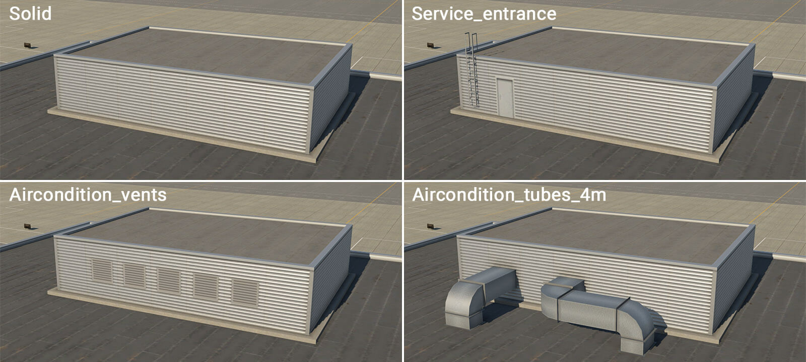
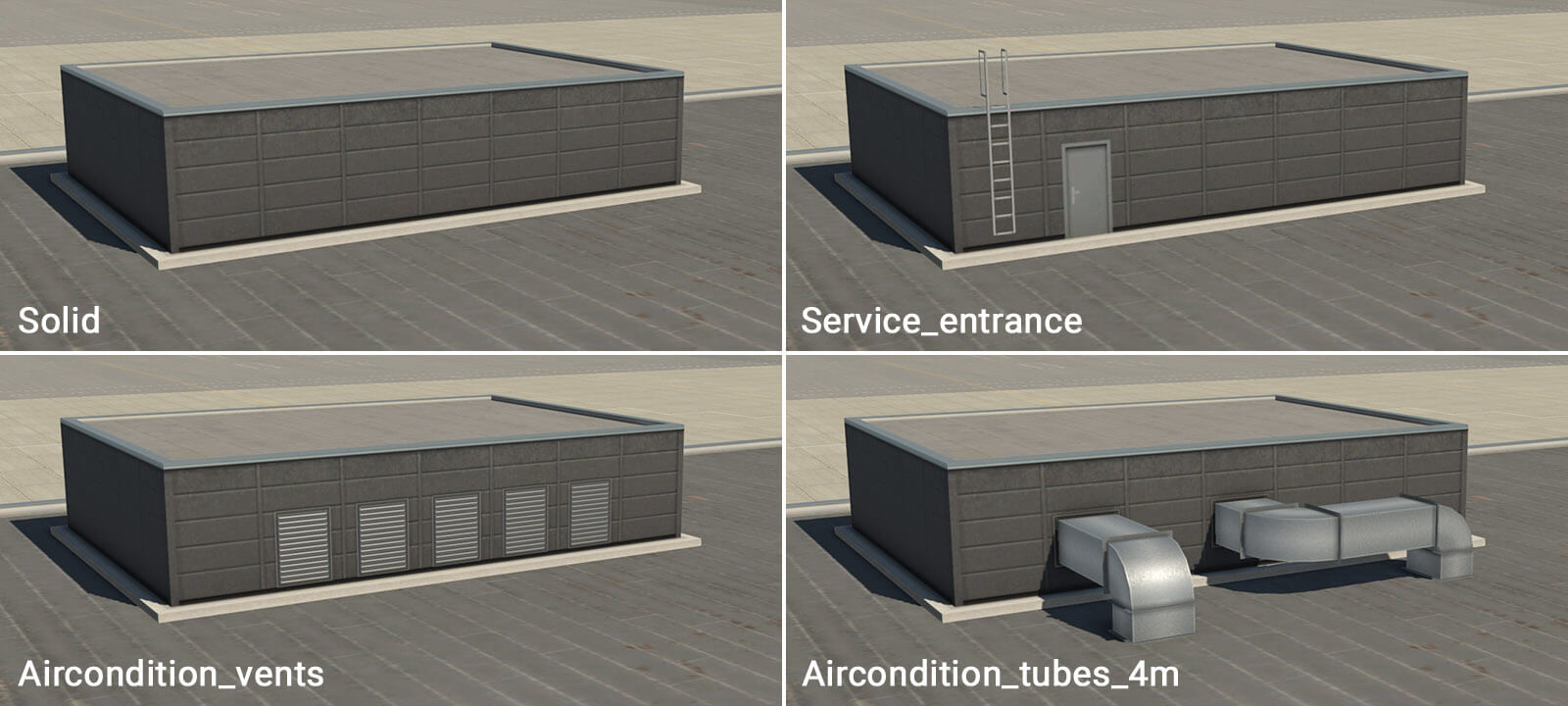
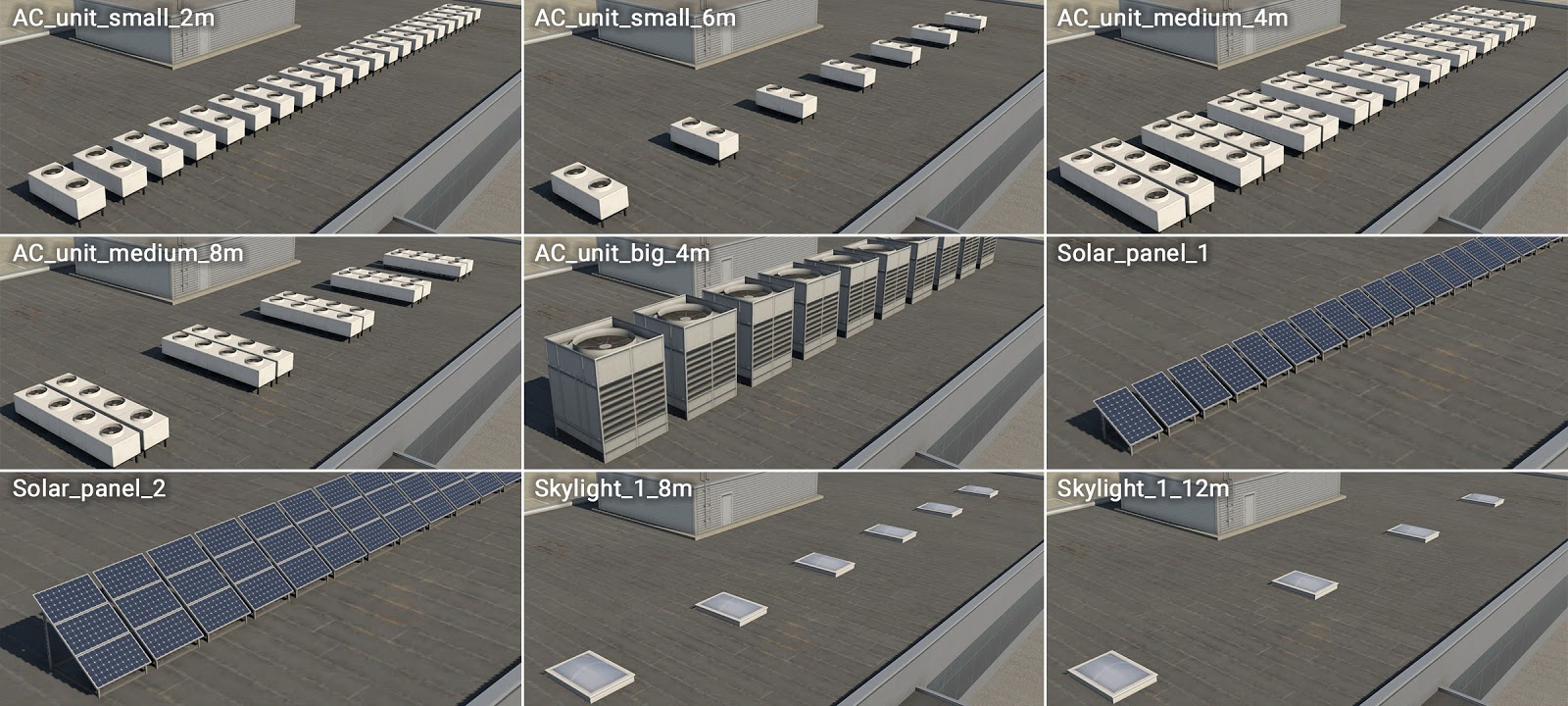
This is a special facade module. The walls and roof are "invisible" and only the attached objects are rendered. This module may be used to add roof elements like air conditioners, solar panels or small skylights. This facade type is NOT a closed path, so artists will see a chain of linear-segments in WED. The attached objects are placed at the center of the line-segments. To change the type of attached objects, set the WALL segment to the items you want to place.
term_roof_elements_01.fac
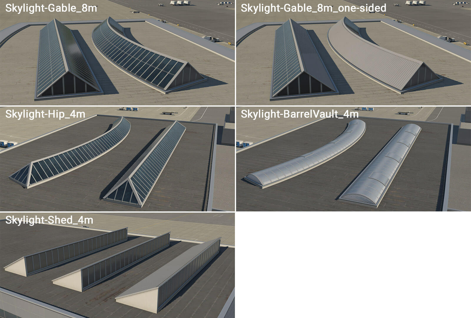
term_roof_long_skylight_01.fac
This is another special module that forms various longitudinal skylights. These are open paths and the path defines the centerline of the skylight.
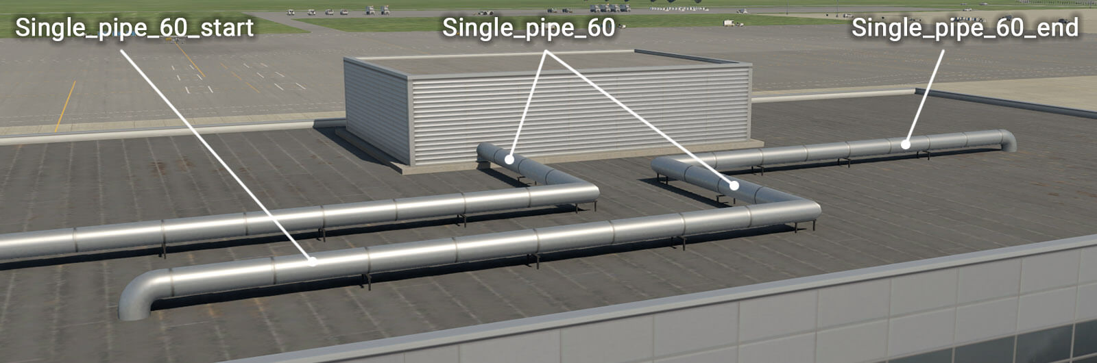
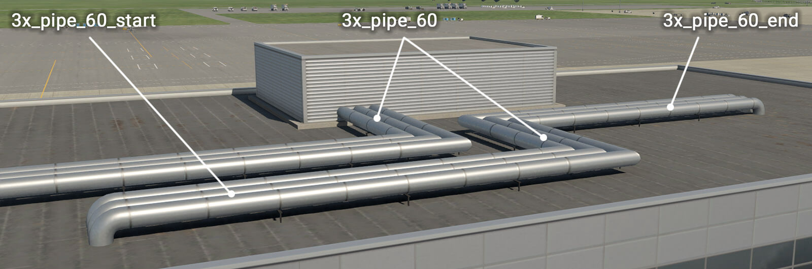
term_roof_pipes_01.fac
Roof Pipes are open path linear elements, the same as skylights. The basic facade wall generates horizontal pipes which can be connected to another module, such as “ _roof_level “. However, there are also special walls with a “ _start ” prefix, and “ _end ” suffix. This is useful when pipes project vertically from a roof. The direction of the polygonal chain in WED is important here, and this is why the artist must define start and end segments for the facade.
OBJ Accents
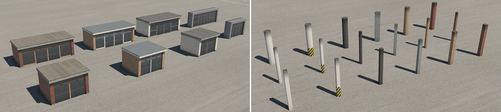
Entrances & Columns
Though some facade wall types include attached OBJs for entrances and columns, some times you just need these elements available stand-alone as OBJs. These entities can be found in the terminal kit groupings for beams, columns and entrances.
For columns, separate ground-floor and upper-floor columns are available and placed manually where required. Columns are available in two lengths – 4 and 9 meters. Shorter columns may be used under “ term_building_Levels ” facade and under “ term_bridge ” and “ term_bridge_joint ” modules (with a height of 10 meters at the lowest position). Higher columns can be used under bridges or joints (with a height of 15 meters at the lowest position). The image below shows typical examples of these entities.